Hi there,
I'm currently working on building my 2005 Kawasaki W650, and am looking at swapping the massive 5 wire ignition switch for a more compact and universal one.
However I'm struggling to understand the stock circuit and how it works, making it difficult to wire in a new switch correctly.
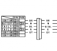
The stock switch is a 3 position switch (putting aside red and blue wires as they're part of the accessory wiring and easy enough to understand)
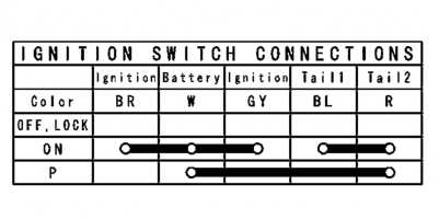
-"Off": no continuity between any of the wires, no power to any of the wires except for the white wire, which sees 12v
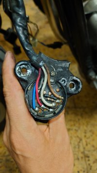
-"On": continuity between white and brown and grey, all labeled "ignition" on the wiring diagram. 12v to white wire, and to brown wire before the circuit goes through to 100 ohm resistor (as you can see on the picture attached) where it then reduces to 6v. 6v to grey wire as well.
-"Park": same as "off" on the ignition side.
Because there's no continuity anywhere on the ignition side when switched to off, I'm assuming the bike doesn't ground a pin on the CDI or elsewhere to function as a kill switch. It seems as if the power of the whole ignition system runs through the ignition switch before being redistributed (which would make sense seeing the size of the white constant 12v wire). Which makes me think I shouldn't use a universal switch which might not be rated for the current the Kawasaki switch uses.
So here lies my questions:
Could I use a relay that is simply triggered by a universal ignition switch ?
What's up with the resistor? I understand it's an anti-theft solution but is it solely responsible for cutting the voltage in half or is their another part of the circuit inside the Kawasaki ignition switch that plays a role?
Thanks in advance for any help, I've been struggling to understand what are my options with this one for the last few days!
I'm currently working on building my 2005 Kawasaki W650, and am looking at swapping the massive 5 wire ignition switch for a more compact and universal one.
However I'm struggling to understand the stock circuit and how it works, making it difficult to wire in a new switch correctly.
The stock switch is a 3 position switch (putting aside red and blue wires as they're part of the accessory wiring and easy enough to understand)
-"Off": no continuity between any of the wires, no power to any of the wires except for the white wire, which sees 12v
-"On": continuity between white and brown and grey, all labeled "ignition" on the wiring diagram. 12v to white wire, and to brown wire before the circuit goes through to 100 ohm resistor (as you can see on the picture attached) where it then reduces to 6v. 6v to grey wire as well.
-"Park": same as "off" on the ignition side.
Because there's no continuity anywhere on the ignition side when switched to off, I'm assuming the bike doesn't ground a pin on the CDI or elsewhere to function as a kill switch. It seems as if the power of the whole ignition system runs through the ignition switch before being redistributed (which would make sense seeing the size of the white constant 12v wire). Which makes me think I shouldn't use a universal switch which might not be rated for the current the Kawasaki switch uses.
So here lies my questions:
Could I use a relay that is simply triggered by a universal ignition switch ?
What's up with the resistor? I understand it's an anti-theft solution but is it solely responsible for cutting the voltage in half or is their another part of the circuit inside the Kawasaki ignition switch that plays a role?
Thanks in advance for any help, I've been struggling to understand what are my options with this one for the last few days!