The Red Wonder
Been Around the Block
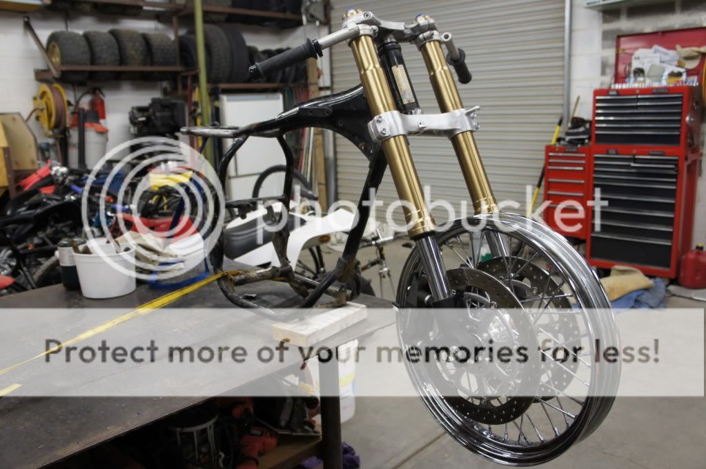
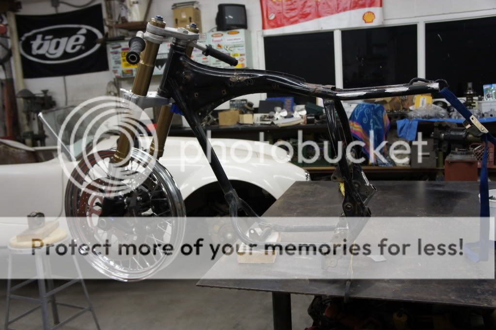
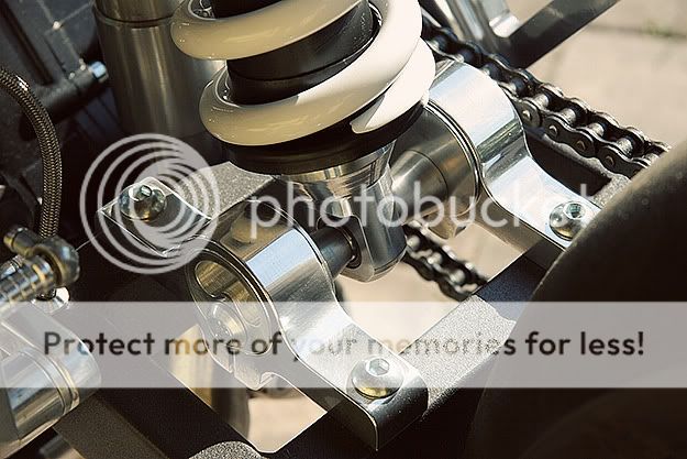
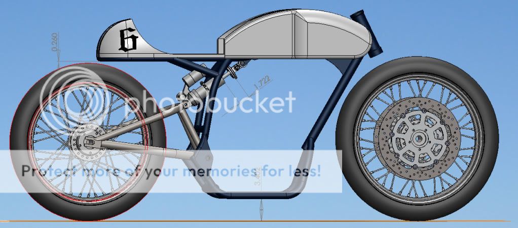
crazypj said:You need to re-think the angle the rear shock is mounted, thats the position about halfway through travel.
BTW, that is the correct hole to drill.
It doesn't completely cure the cam problem but it definitely helps
What do you mean that is the position half way through the travel? As in, that is where the bike should sit when it is half way compressed? Because I can set and determine all of that with the rear swingarm...also this the beauty of drawing everything before making sparks! In that picture, the shock is fully extended. I was trying to that figure out actually, what is a standard ground clearance for one of these bikes? I never took measurements on mine when it was still together :-\ . From scaling photos of other bikes, I have come up with about 7-8 inches to the bottom frame rail from the ground, and about 4 inches from the top of the rear tire to the bottom of the rear of the frame. I was shooting for aligning the rear shock along a line from its top mount, to the rear axle when it is static.
I just calculated out the ratio, and for every 1 inch the damper compresses, the frame drops 2.1...so a rocker ratio of 2.1, which mean that the spring rate might not be too far off.
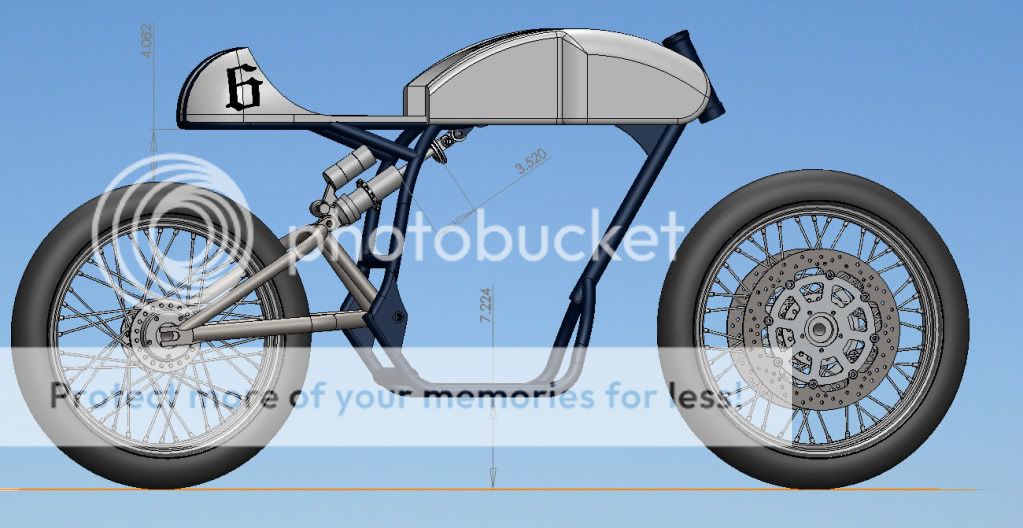
You are right in that I won't use the full travel of the shock, but it will be close enough. I figure with me sitting on it, the bike should only drop about an inch, but that is just a guess. I have no idea what the spring rate is for that shock so I can't calculate it. If anyone knows what it is, please let me know!
Can you elaborate on what you mean PJ? Thanks!
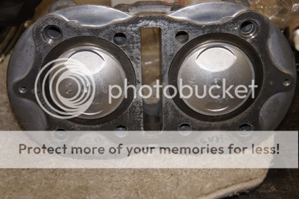
rockcitycafe said:if you have access to a machine shop, why not convert the cam to roller bearings. widening those holes I figured out, decreases the flow to the bottom half of the engine, starving the bottom end, which it turns out, starts to destroy your small end bearings... with the needle rollers, the only oil needed is excess from the cam tubs, and they won't chew the head to pieces if they fail
I read your blog about that, and it is something that I have seriously considered. I saw that you had to press a steel sleeve on to the cam because the cam metal itself was too soft. When you machined those parts, did you do it with the head and the rocker box bolted together, or apart? I have a spare head and rocker box that I could try this on before committing to eating the newish head that I just bought.
Are there any parts that I am missing from the list to do this mod:
1 - 28mm OD x 22mm ID x 20mm width needle roller bearing
1 - 28mm OD x 22mm ID x 12mm width needle roller bearing
2 - Sizes?? Thrust bearings for the side to keep cam centered
Machining -
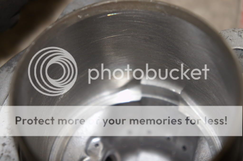
- Machine 28mm holes for cam journal needle bearings
- 28mm plug to fill the hole
- .090" from each side in head to allow larger thrust bearings
I've tried to do my homework as much as possible for this and if I find that it is all with in reason, than I will go ahead and do it!
I had actually posted a reply to the original thread of yours hoping to get some answers too, so if you could help me out, that would be great! http://www.dotheton.com/forum/index.php?topic=17373.10
I have been admiring your work and looking to mimic some of the mods you made, even the spare rocker box cam aligning trick! Thanks again for the help!!
Also, can you provide a little more enlightenment on what you did to help oil the center journal? I couldn't see that in any of your pics, thanks again!
")