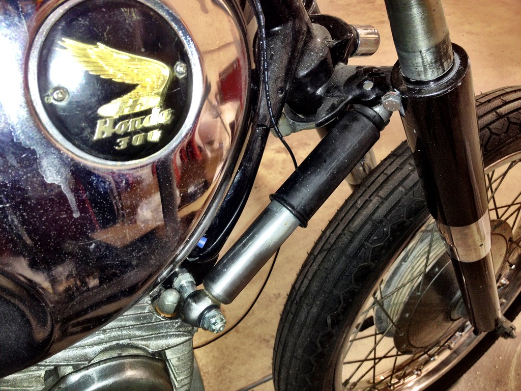
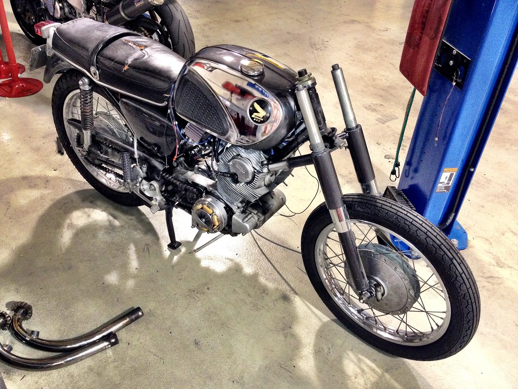
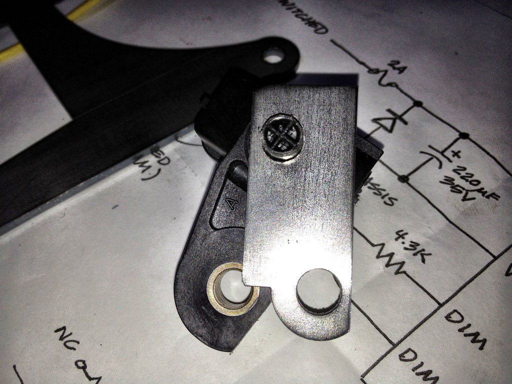
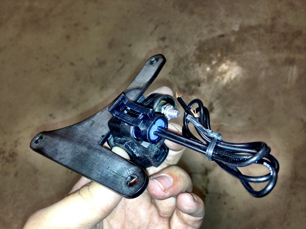
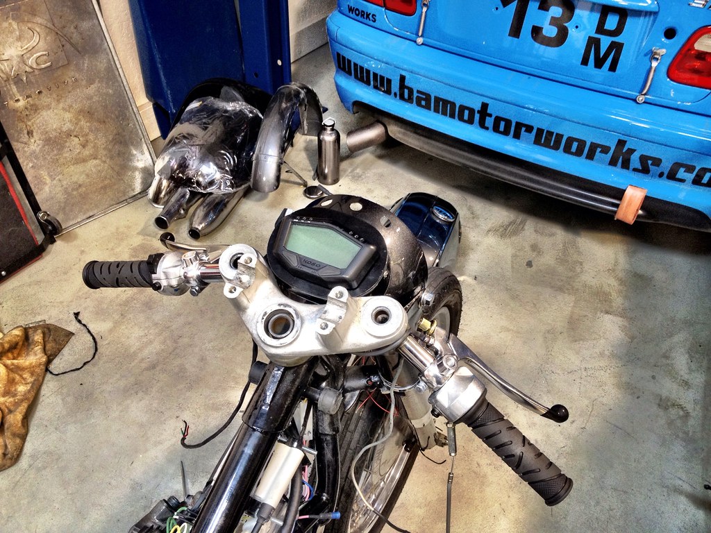
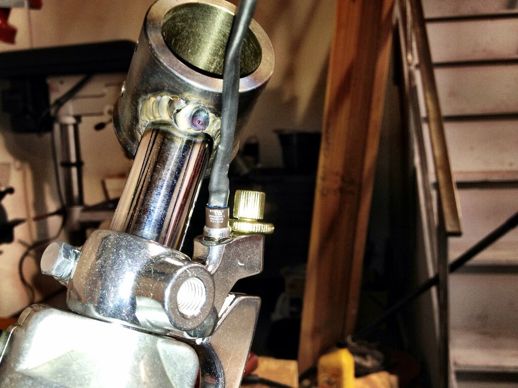
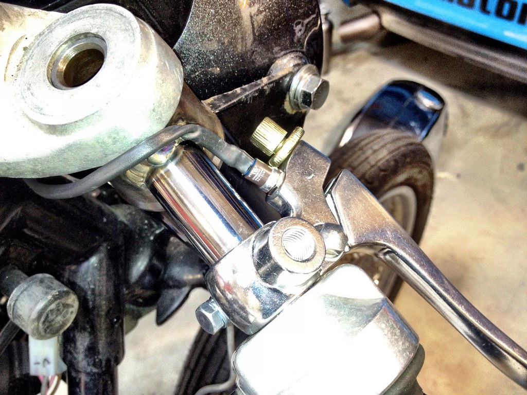
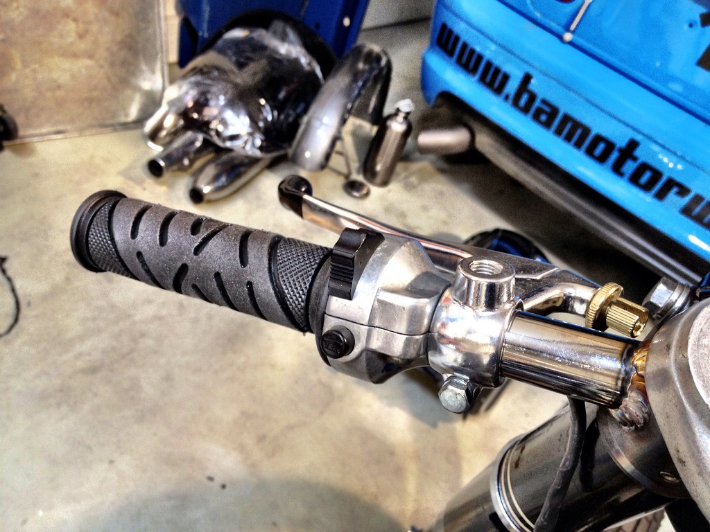
Alright, haven't had a huge amount of time to work at this stuff, but I did get a couple steps done. First off, I got the bars on. This wasn't a difficult process, just involved a few more well-placed holes drilled without weakening the relatively thin steel. I routed the starter, horn, and high/low beam wires through the holes, down the bars themselves, out another small hole in a slightly less conspicuous spot by the triple clamp, and into the headlight case where they will meet up with the main harness and LED headlight. I found out that the JC Whitney/EMGO brake and clutch levers are based off the Honda CL/CB72/77, so they look exactly the same as my stock ones but shinier and with some condoms on the tips. The brake lever boss even has a little hole that, I assume, is for some front brake light switch. Now that would be a big improvement for this bike. I don't use the rear brake all that much, and it's a choice between setting the rear brake switch too high as to flicker or so low that you really have to be serious about stopping to trip it. Having a front brake light switch would be outstanding. Unfortunately, EMGO is out of Thailand or someplace and nobody was around to tell me what that part is supposed to be. All the easily available non-hydraulic brake light switches I found online were
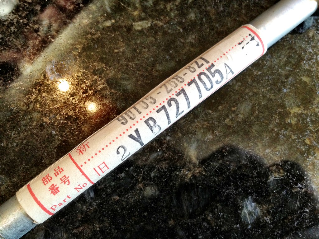
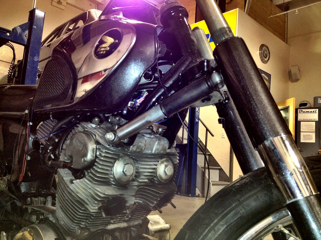
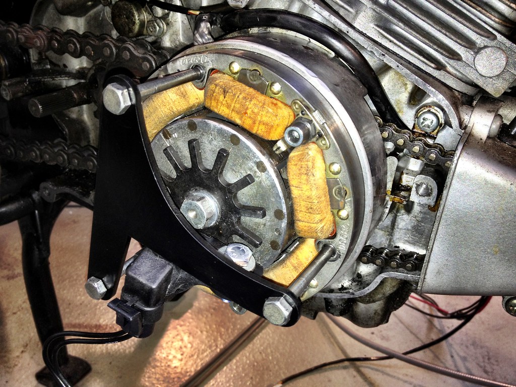
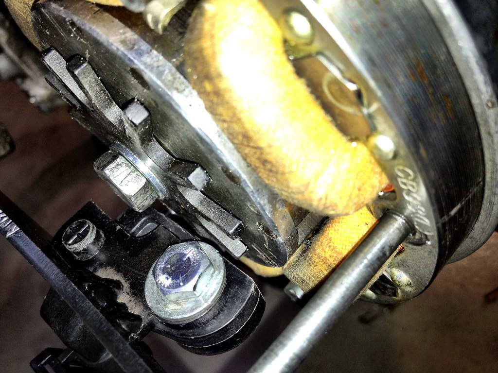
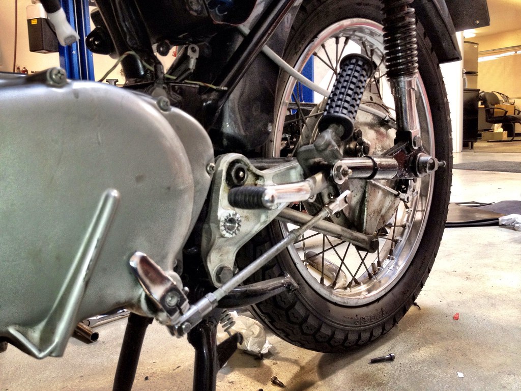
way too big to fit where I need it. I went to my electrical fallback: Radio Shack. They had some little momentary, normally-open switches that roughly fit in the little hole. I epoxied one in (I'm going to say 50% of this bike is now epoxy) with a little #4 nut on the end to reach the switch point. It works fine, if it's a bit ugly. I also had some time to install little thing like the longer shift rod after some clocking of the shaft. It looks a bit weird being that long and is kind of hard to use with that long shifter, but it should be fine for every day use. On the hydraulic steering damper front, I had to order the special angled bolt that replaces one of the front engine mounts. It is a whopping $75 (SEVENTY-FIVE DOLLARS!!!) since they are so rare. As stupid as that price is, it's kind of like gum at the airport, where you going to go for a better price?
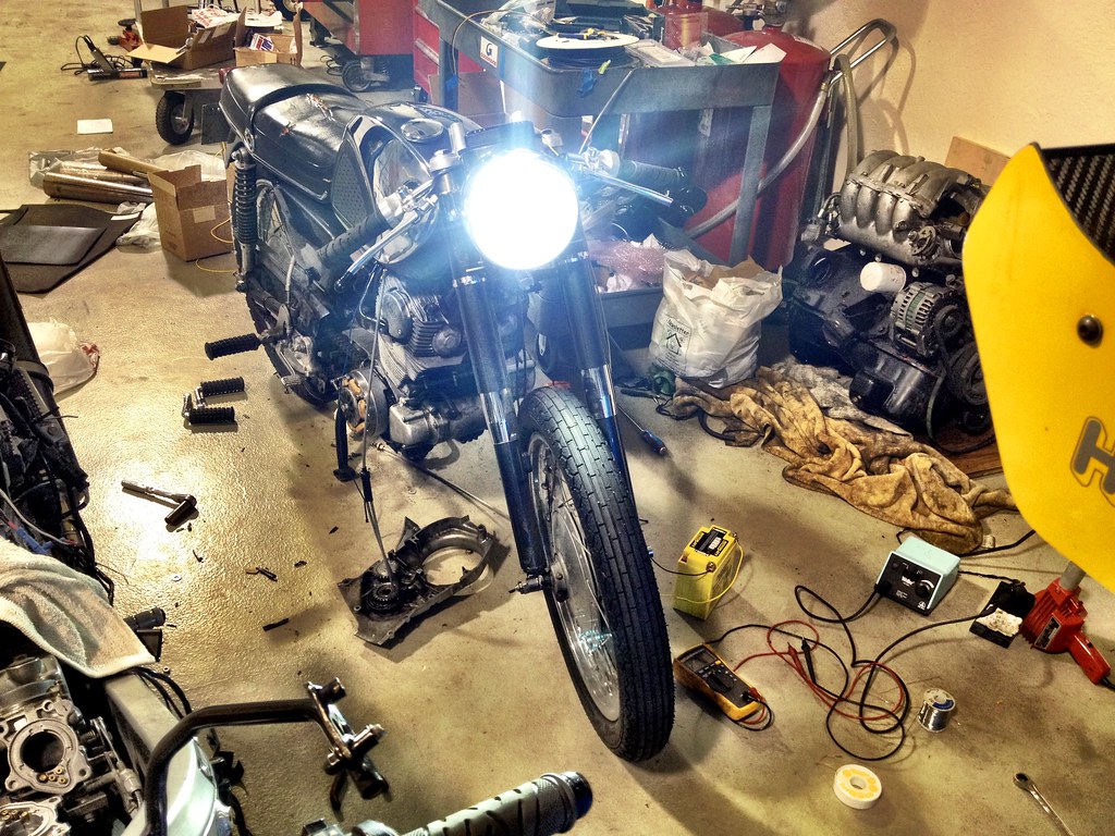
The LED headlight went in to the bike with the correct wiring so I could test it all out in the proper application. It work pretty damn well. With the high beam on it uses about 15W, with the low beam on, it uses a measly 3W. That's 1/3 of what the stock taillight used, about 12% of what the stock low beam required! I don't think I'll really use it for night riding, but it'll certainly keep the piggies off my back for needing a light on during the day.
Below are a few more videos of testing the light throughout the finishing touches:
http://www.youtube.com/watch?v=VlrxBZ3165A
http://www.youtube.com/watch?v=hjUHdeP7XbI
http://www.youtube.com/watch?v=kiaZU2QWm5Y
Pictures:


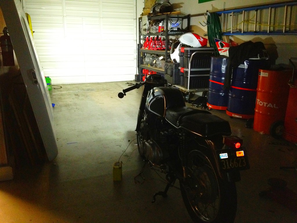
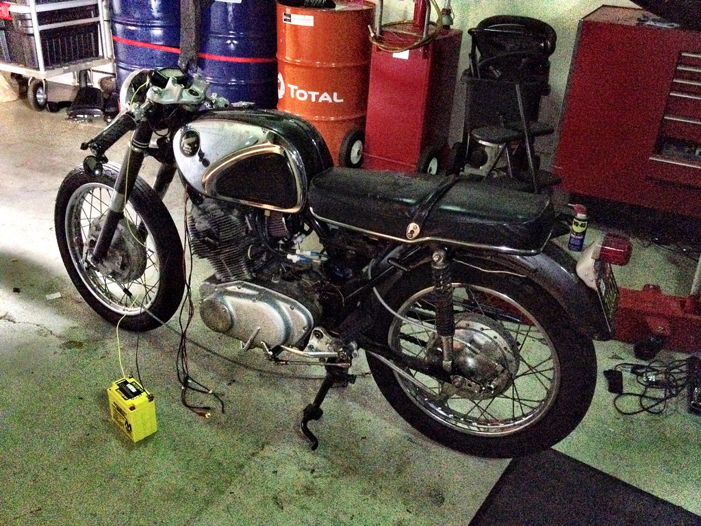
")