Follow along with the video below to see how to install our site as a web app on your home screen.
Note: This feature currently requires accessing the site using the built-in Safari browser.
We noticed you are blocking ads. DO THE TON only works with community supporters. Most are active members of the site with small businesses. Please consider disabling your ad blocking tool and checking out the businesses that help keep our site up and free.
So I'm in getting close to wrapping up a project 81' CB750F and have everything but the upholstery and wiring complete. I have the upholstery figured out but the wiring is kicking my ass and can admit when I'm out of my element.
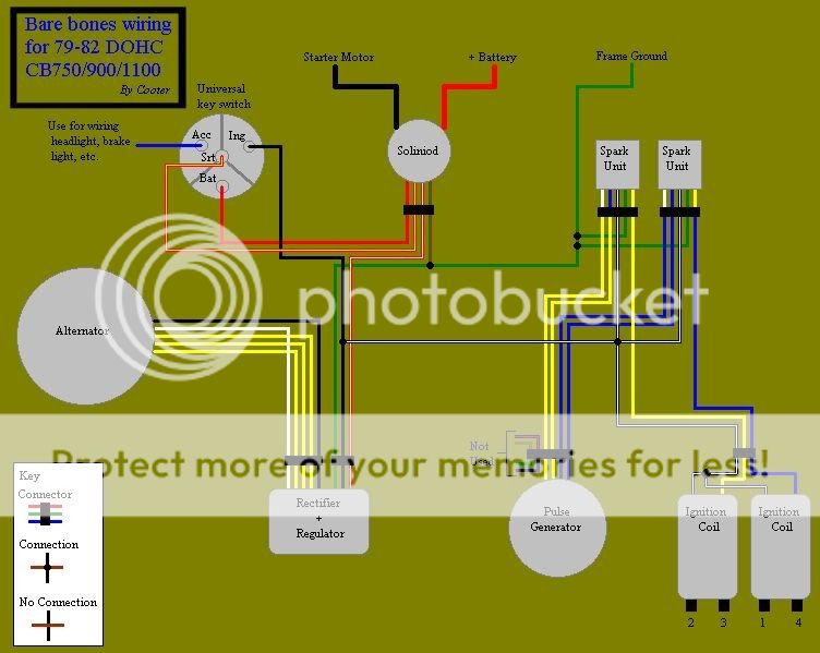
Looking at schematics is like looking at hieroglyphics to me so going off the factory diagram has gotten me nowhere. I've decided to follow the below wiring diagram for a basic wiring but I also plan to run turn signals (I'm using a Sparckmoto flasher relay and a 3 position toggle switch) and a hi/low headlight (on/off toggle switch mounted in the headlight bucket) and an Acewell gauge
I decided to use a 4 position ignition and luckily enough this wiring diagram goes over the wiring for that, but I was hoping someone here might be able to shed some light on what I should be doing for the rest for the accessories I plan to use.
My hope is that I can have the 3 pin on/off/on toggle switch control the turn signal and the on/off toggle control the high beam. (headlight will always be on so the switch will control the high beams only.
Can anyone chime in and tell me if this is an easily attainable goal or am I making things harder than I need to?
If it were me, I'd use use a three pole on/on toggle switch for the headlight, though. One setting is just low beam and one setting is just the high beam. I have about 20 extra of these types of switches I can mail out, if you need one. I ordered them by mistake and they're just sitting around.
Lets focus on the turn signals first, though.
The wiring run for the signals is pretty easy. One wire from a power source to the relay and then from the relay to the middle pole on your switch. Each of the outer poles on the switch will be left or right. From each outer pole, run two wires. One to the front turn signal and one to the rear turn signal. Each signal then gets grounded and you're done.
So for power to the flasher relay, would it be a good idea to run a wire straight from the "Accessory" position of the ignition or would I be OK to just draw power from some other source that's physically closer to the relay? Any you'd suggest?
My relay is mounted here:
And my ignition is mounted in this tab:
I'm trying to accomplish all this by tweaking my factory harness rather than adding new wires as much as possible so I can retain the original color code.
Sounds like to do that I should be pulling the left/right bank turn signal wires (Pretty sure they're solid orange / solid baby blue) and running them to the outer poles on my switch, then to the signal.
As far as ground, is it OK to run them all to any ground in the harness? If that sounds correct I can knock that out and report back.
I'm regretting not buying a harness from you now...
About the on/on high beam switch - I drilled a 1/2" hole for my existing on/off switch. If the ones you're talking about aren't micro switches and don't need a smaller hole than what I already have I'd be down to get one from you.
Just hook shit up and see if it sparks.... sounds like your in the right track and Sonreir is an excellent source no? You can hook your ground anywhere, it's all common. You can go straight to the frame if you like. I would get your power from whatever is close, to your relay. Tap into the tail light maybe since that has to pass by close to your relay. Keep up the great work. Can't wait to see it finished.
I'd tap into the black wire feeding your regulator. Easy spot to get to, usually. Then you run a gray wire from your flasher to your turn signal switch.
So using your advice I was able to the sort out the above simplified wiring diagram and run power to the turn signal switch through the flasher relay.
As I'm getting into this though I'm realizing that I over simplified my end intentions by not figuring in the brake light and both brake light switches.
I also noticed that the wiring diagram I posted has no fuses. Should I be running a fuse somewhere between the red wire going to the "BAT" input on the ignition, or somewhere else?
Lastly (I think) is using the "accessory" terminal off the ignition a good source for power for the headlight?
15A should do it. Fuse goes between battery and ignition switch. Make sure the connection from the R/R to the battery is before the fuse (basically run it straight to the battery).
ACC or IGN pole on the switch is fine. The ACC pole is on with the first and second click of the key and the IGN is on with only the second click. A lot of folks treat is sort of like parking lights.
For brakes, you need power going to the front switch and the rear switch. Coming out of each switch are the brake wires which then get spliced together and go to the brake light.
Neutral and oil lights work the same way as one another. Each light gets constant power and then the grounds head straight to their respective switches.
So the diagram I posted has 2 wires at the pulse generator connection listed as "not used". From what I can tell those are the neutral indicator light and the oil pressure light (blue/red and teal/red).
Would simply leaving the blue/red wire and the teal/red wire from the pulse generator connector inplace and running them to the warning lights in the Acewell gauge be sufficient?
Though it's worth noting that I thought that was a six pin connector, not eight. Aside from the four wires for the pickup, the neutral light wire, and the oil pressure light wire, I'm not sure what those two others are meant to be.
Do you have to use that Neutral switch diode if you use only the neutral and not the clutch? My neutral switch is not working and I can't figure out why?
Do you have to use that Neutral switch diode if you use only the neutral and not the clutch? My neutral switch is not working and I can't figure out why?
I have the gauge mostly wired, I just need to wire in the high beam switch. All the other supported functions seem to be working as intended.
I am however hitting a wall on the tach (yellow wire) from the Acewell. I'm trying to figure out what wire on the coils to tap into to hard wire it. Any suggestions?
I'm not sure on this, but it should just read pulses from the coils so you could go to any of the output terminals on one of the coils. Maybe put a test light on there and see which one "Pulses" I have a new custom gauge coming from speedhut that is going to be the same way so I'm curios here....
I've read from a few other forums (not cb750 specific) that claim you tap into a wire on the input side of the coil.
This gauge has been fairly similar in colors thus far so I'm wondering if it could be as obvious as attaching the yellow wire from the gauge to the yellow wire coming from the spark unit going into the coil?
I'll hold out for some confirmation before making any moves.
This site uses cookies to help personalise content, tailor your experience and to keep you logged in if you register.
By continuing to use this site, you are consenting to our use of cookies.


 sounds like your in the right track and Sonreir is an excellent source no? You can hook your ground anywhere, it's all common. You can go straight to the frame if you like. I would get your power from whatever is close, to your relay. Tap into the tail light maybe since that has to pass by close to your relay. Keep up the great work. Can't wait to see it finished.

