deviant said:
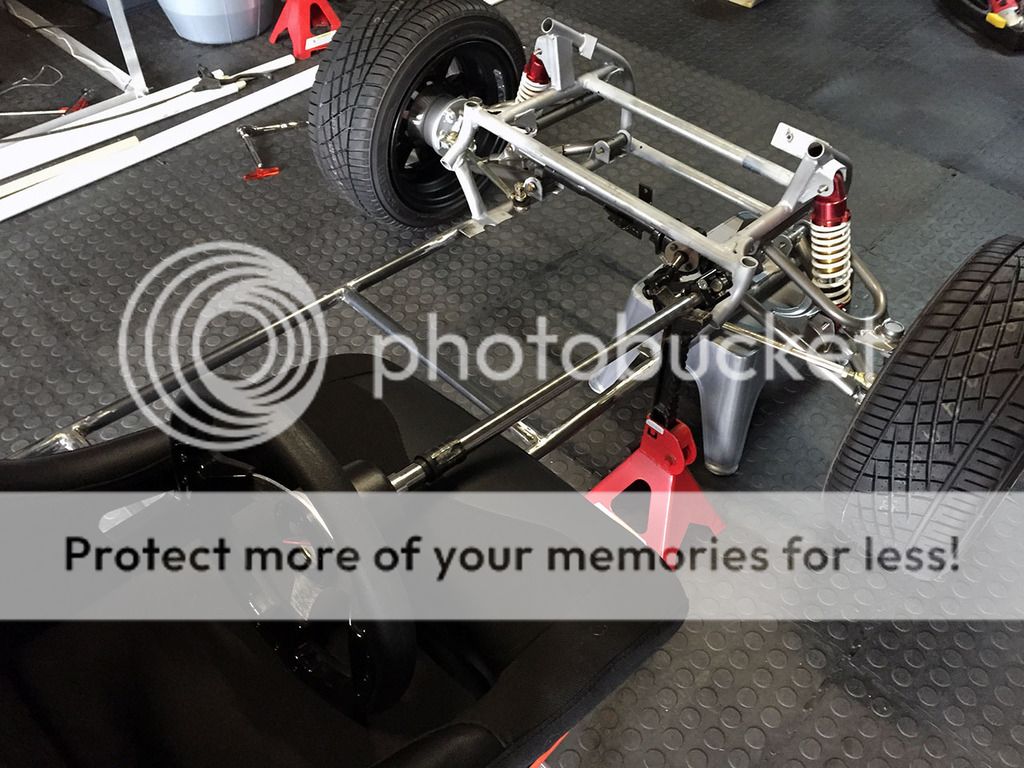
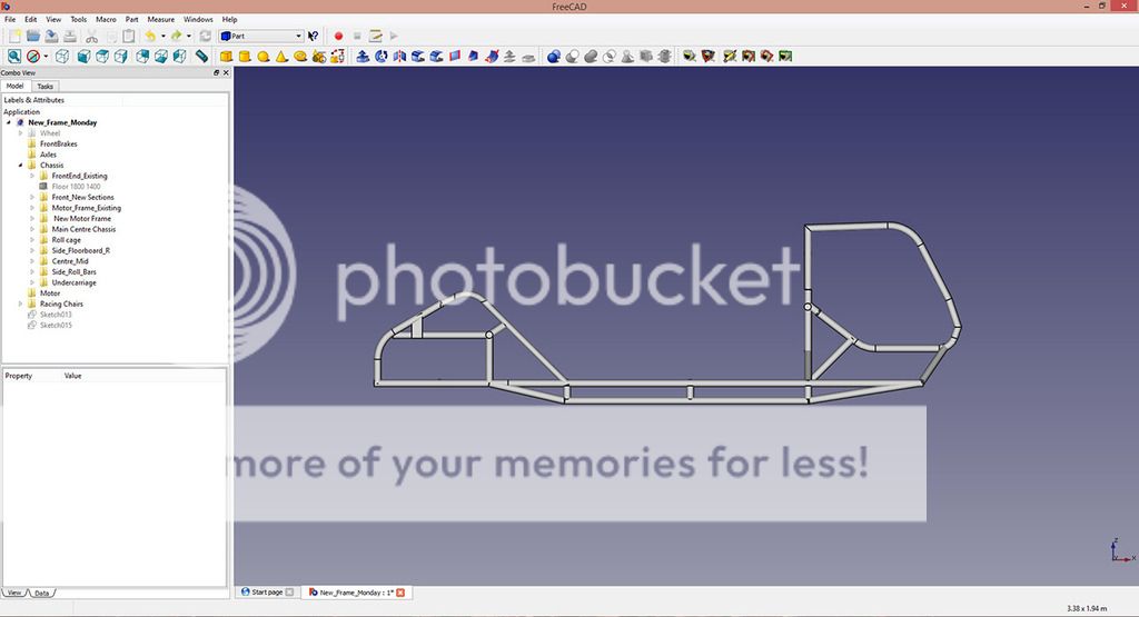
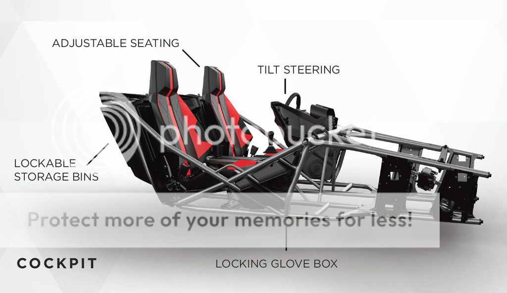
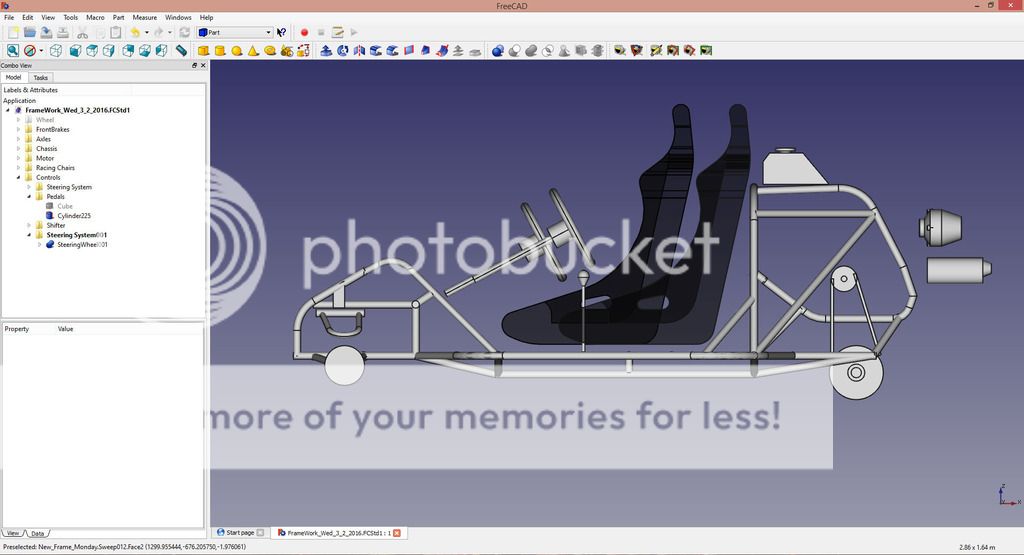
Ever looked at kart chassis? It's crazy how flat they are.
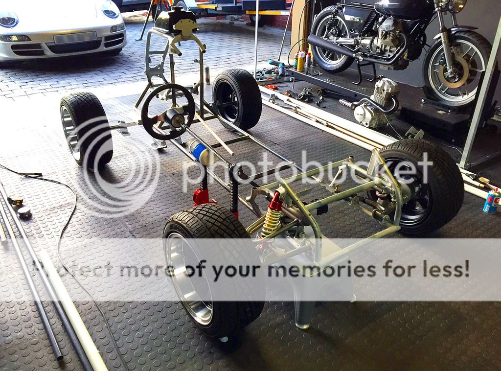
Thats a pretty badass looking kart chassis. Never seen one with this front extension / or is it the front wheels pushed further back design. ?
Tune-A-Fish said:
I love this thing and when I get caught up I'm gonna attempt a single seater much like this.
Nothing less than 600cc with discs and suspension all round OK!!??

Letze said:
Deviant, part of circle track and super kart design is chassis flex, they're actually designed to lift the inside rear wheel when turning. this is necessary to counter the under steer presented with the solid rear axle. The same thing happens on an ATV with a solid axle but under different circumstances, normally with the chassis rolling towards the outside letting the inside front and rear rise. Since the front is sprung it maintains it's connection with the ground, but the inside rear will rise as it shares its suspension point with the outside.
I'm curious to see the solution Dale come sup with.
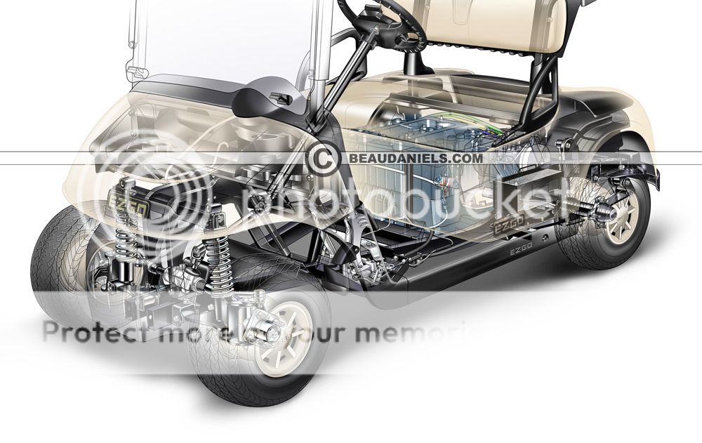
When I first started thinking about how to do this project, I was going use a golf cart chassis as the donor.
Its got pretty much everything you need.
Steering system, suspension all round, diff, linear torque etc.
Downside for me was the cost of batteries, charger and new electric motor, the general size of the golf cart felt a little small to me as well.
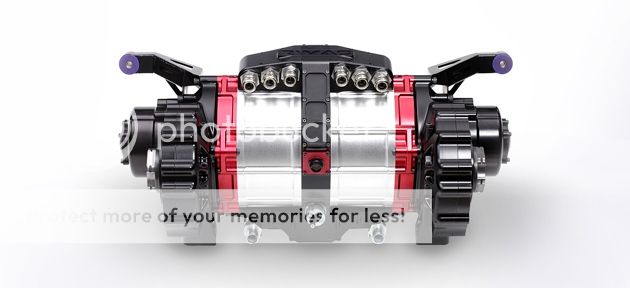
... and if you thought an electric motor couldn't be sexy, check out Rimac's Supercar electric motor:
http://www.rimac-automobili.com/en/
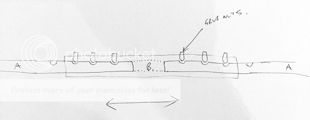
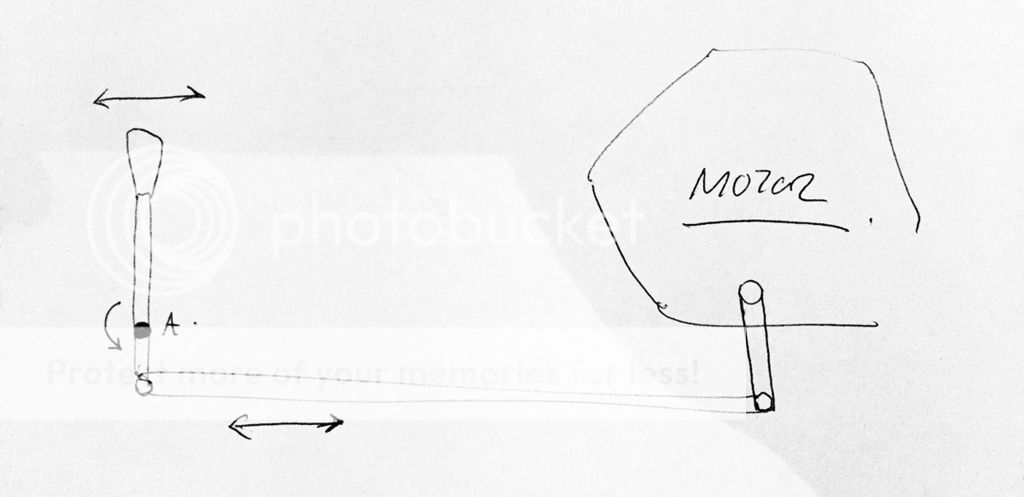
Getting back to the Diff - man, this is a tricky one!
Im not sure how the motors drive shaft can be connected convincingly to a diff, and also, that way, you're cutting out chain drive and taking sprockets out of the equation... Unless Im missing something here? Any ideas / thoughts?
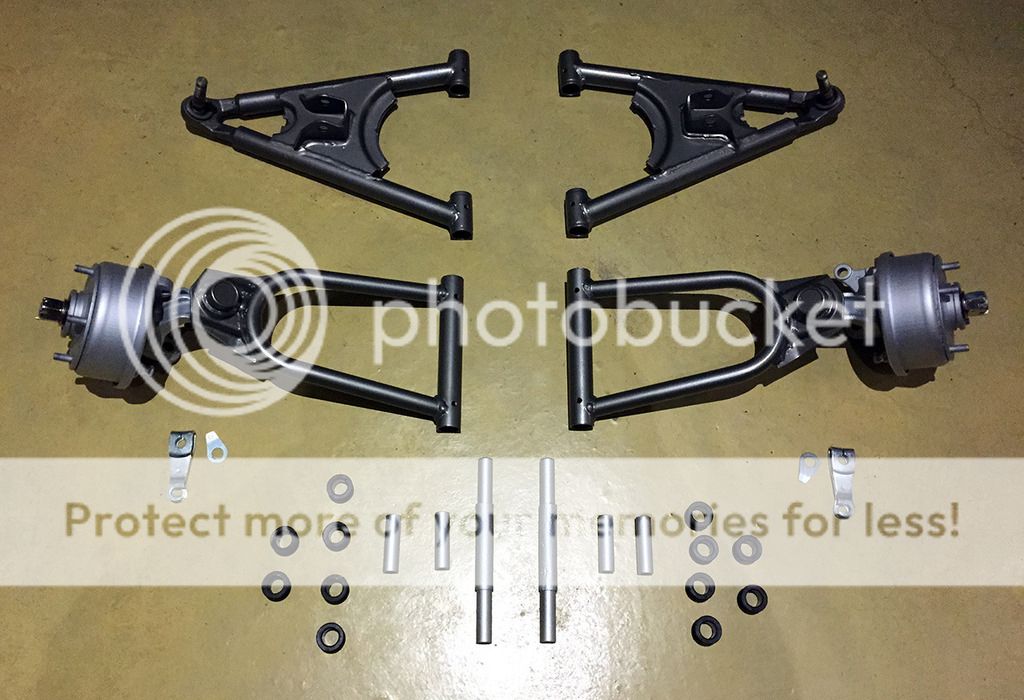
I was just going to make a 31.75 mm tube axle, running in a couple of self aligning bearing units, with a sprocket.
But you've got me thinking! Dang!
DohcBikes said:
No, but a couple of us are.
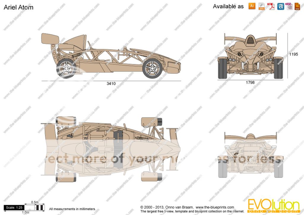
The atom frame is designed for a heavier car with a much more powerful engine. A design such as this would be overkill, therefore detrimental to performance.
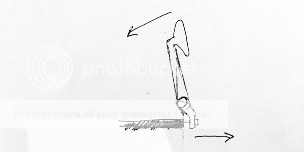
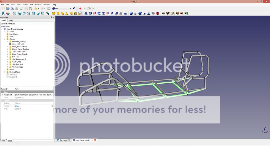
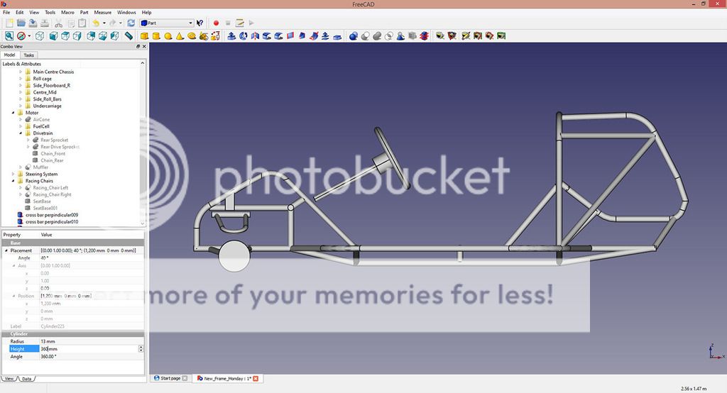
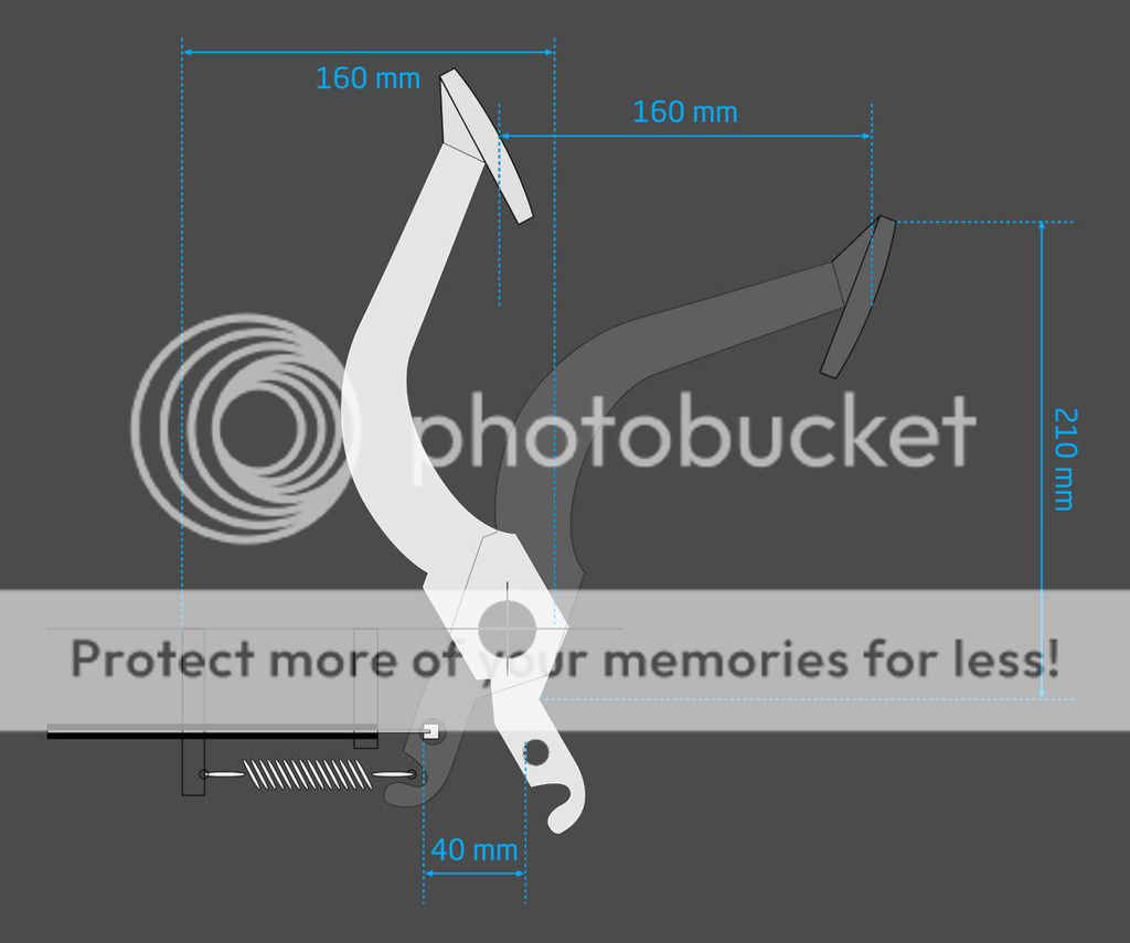
Yes, your revised drawing shows the basic concept of what needs to happen imho. In the previous configuration, there are still 2 points that are going to recieve a large amount of load at times. The revision does a much better job of distributing the load throughout the chassis, because it is directly tied to more of the existing design.
Gotcha!
el barto said:
Thanks buddy!
This is turning out to be a lot of fun!