Follow along with the video below to see how to install our site as a web app on your home screen.
Note: This feature currently requires accessing the site using the built-in Safari browser.
We noticed you are blocking ads. DO THE TON only works with community supporters. Most are active members of the site with small businesses. Please consider disabling your ad blocking tool and checking out the businesses that help keep our site up and free.
Your 100% correct, it is a bit like riding a bike with leathers, better in 10C than 40C.
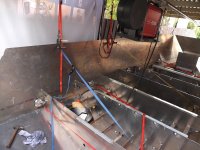
Weather was very ordinary, you can see the awnings I set up to block the wind an rain from blowing in.
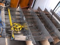
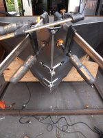
Alright, all the stringers and frames are tacked in. It took a fare amount of effort to pull plates in and stringers down, but every piece is on its mark.
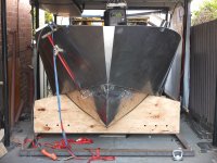
Next are the reverse chine plates and sides. This boat has the chines angling down rather than just flat, to help with stability at rest.
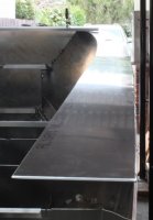
Put the reverse chine on today. The bow was challenging as the bottom plates were not quite fair and it needed a considerable amount of pulling to get it all together and fair (smooth lines). To borrow a topical phrase, I have emerged from the dark side of the moon. I will post some photos tomorrow. Hope to get get sides on tomorrow.
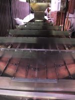
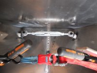
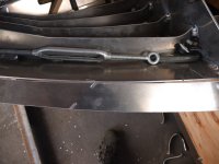
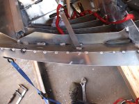
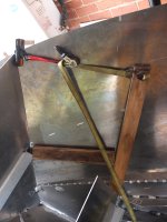
in the following photos, the first is as it was as I lay the reverse chine against the bottom plates and the gaps that were there. The second photo show where I put the turn buckle to pull the bottom plate in and the ratchet strap used to pull the bottom plate out so that the reverse chine went on without gaps. Happy and relieved with the final result.
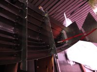
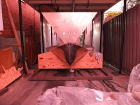
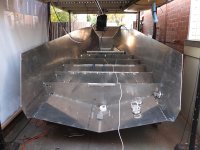
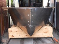
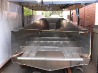
Weather has been better this weekend. After get the chine on straight yesterday the sides went on without too much drama. I still needed to pull and push onto the chine at the bow. Lots of tacks and they get closer as it approaches the bow. Looks like a boat now, so all the big construction is done. The slower fiddly work will begin.
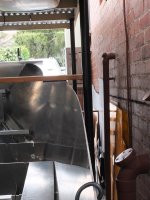
Glad I did not consider getting a bigger boat, as it is only just fitting in the space.
Did not get much done this weekend as I went up to my parents farm and installed a solar powered automatic gate.
https://www.youtube.com/watch?v=Ojid6f42enA
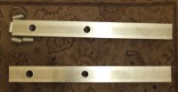
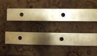
I did cut and drill the 2 load bearers which will be welded to the transom plate. The plans do not include crush tubes, but I am going to use a crush tube in each hole for mounting the outboard engine. I think the MIG will just melt the bejesus out of the joint, so I am taking it to work and get someone with more skill than I to TIG the crush tubes into the bearers. By using the crush tubes I should be able to get a much better seal around the outboard mounting bolts.
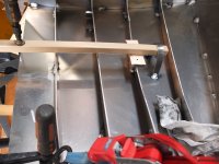
Very happy I asked about welding in the toque tubes. The box section is 60 X 40 X 4mm, so I had cut the torque tubes 40mm long - wrong! To get a good weld the tube surface needed to be set back and the TIG weld built up to the top surface of the box section. I need to turn the tubes down to 36mm long so they were set back 2mm on each end. Photo shows the end result with the weld fully built up and then sanded down to the box section surface.
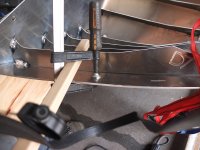
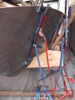
Pulled the bow together and stitched it up. Then used a couple of bits of wood and a ratchet strap to push the anchor well frame into position on the side plates and tacked it in. Seriously thinking I will call the boat "Ratchet" after the most used tool to build this boat!!!!! ;D ;D
Finally before I ran out of argon, I welded the load bearers onto the transom plate, tacked in the final bay of stringers to the bottom plates and then tacked the transom into the hull. I will get some argon tomorrow and hope to get the gunnels on to set the final hull shape before I start to weld it out.
Good question - not sure I would call it a feature, but with the amount of structure in it, it is designed to accommodate the in built stress. When you build in plywood you can avoid the stress by building up layers of thinner material in laminations (cold molding). You cannot do that with alloy, so it is a matter of forcing it and then containing the stress.
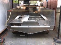
A bit more work on the transom. Gunnels are on, and created a bit more inbuilt stress.
Next weekend will be spent welding out the inside. All stringers and all plate seams.
This site uses cookies to help personalise content, tailor your experience and to keep you logged in if you register.
By continuing to use this site, you are consenting to our use of cookies.