
We noticed you are blocking ads. DO THE TON only works with community supporters. Most are active members of the site with small businesses. Please consider disabling your ad blocking tool and checking out the businesses that help keep our site up and free.
You are using an out of date browser. It may not display this or other websites correctly.
You should upgrade or use an alternative browser.
You should upgrade or use an alternative browser.
Project CB690 (KTM 690 engine in a CB550f frame)
- Thread starter goodoltup
- Start date
goodoltup
Been Around the Block
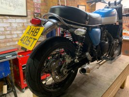
Plate attached, road grime acquired! I took it for a few test rides, but the roads are still damp at best, and the temperature outside is still quite cold. I had one moment where the back end stepped out a bit when I gave it too much coming out of a slow corner, that was enough to make me VERY cautious for the rest of the ride. I won't be able to actually give it some stick until at least March. But, in the times that I could get on it, I was very impressed. It is VERY quick. It doesn't care what gear you are in or how low the revs are, it just pulls. It is savage. Just what I wanted.
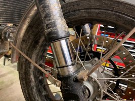
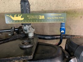
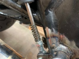
Note that the zip-tie telltale shows that it very nearly bottoms out. This was a pretty normal ride with no wheelies or panic stops, and it is still only 20mm from the end of the fork bottom.
Note that the zip-tie telltale shows that it very nearly bottoms out. This was a pretty normal ride with no wheelies or panic stops, and it is still only 20mm from the end of the fork bottom.
Attachments
goodoltup
Been Around the Block
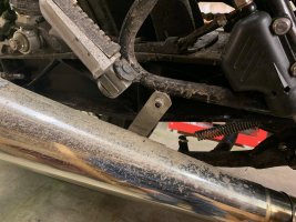
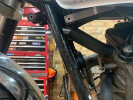
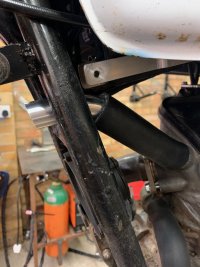
Shifter is sorted. I took the stock shift pedal and bent it in a vice to shorten it some, and removed some material from the sprocket cover to eliminate interference. It is around 140mm on centre from the peg, whereas my CD175 is 130mm. I think this is just about right, it feels good under my boot and has good action. Last two pictures show how close it is to the frame rail and the sprocket cover in up and down positions.
Attachments
goodoltup
Been Around the Block
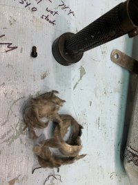
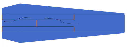
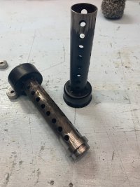
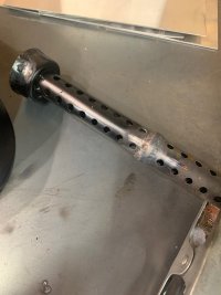
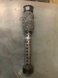
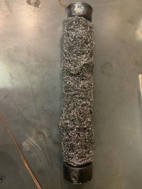
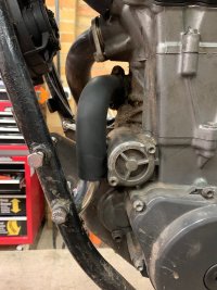
New idea for the exhaust. I took two of the cheapo exhaust db killer inserts and turned them back to back, and made a connector between them. Now the exhaust must enter the perforated tube, go through steel mesh (kitchen scrubby) go back through the perf tube, and then exit the muffler. In the diagram the black lines are perf tube and the orange lines are solid. I tried it out and it IS quiet, but there must be a ton of back pressure. I'll see on the next test ride if it responds ok.
Attachments
goodoltup
Been Around the Block
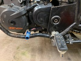
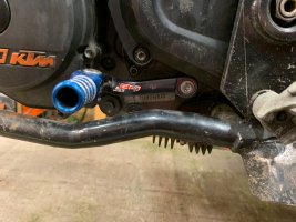
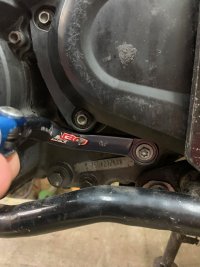
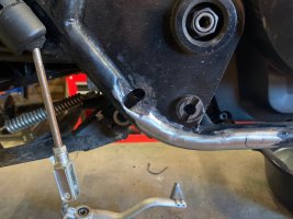
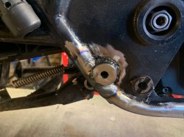
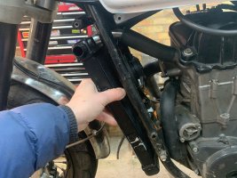
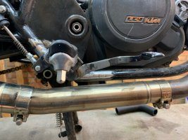
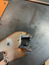
New idea for rear brake. The pedal originally pivoted around the footpeg, and the mounting location of the master resulted in an actuating lever that was too long, and the brake had a wooden feel with almost no travel. I could either move the master or move the pivot, I chose move the pivot. Instead of pivoting around the footpeg, now it will pivot around the boss shown. This will make the actuating lever 35mm, which matches what it was on the KTM.
Attachments
goodoltup
Been Around the Block
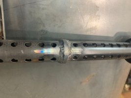
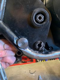
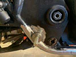
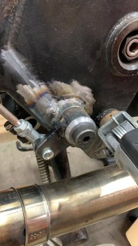
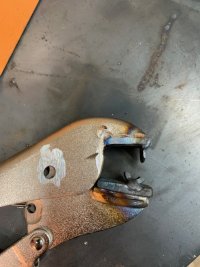
The threaded boss that was made (by my neighbour with his new lathe) overlapped with the frame tube by about 50%, so something needed to be done. Steps as follows:
1. Make a pig's ear of the frame
2. Weld it up and hide the shame.
Looks fine in the end, really. A little weld dressing and paint and no one will ever notice.
1. Make a pig's ear of the frame
2. Weld it up and hide the shame.
Looks fine in the end, really. A little weld dressing and paint and no one will ever notice.
Attachments
goodoltup
Been Around the Block
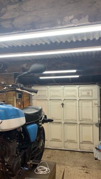
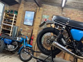
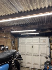
Quick one, I installed LED T5 lights in the garage. They're great. Cheap (£70), and super bright. The garage is only about 14 feet by 25 feet, and I put 8 T5s in there, plus some other shorter ones over the bench. Only problem is the colour temperature is super high, 6500K. The light is very cool, almost blue. I ordered some colour correcting gels to see if I can warm it up a little.
Attachments
goodoltup
Been Around the Block
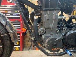
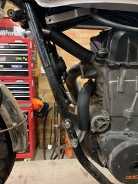
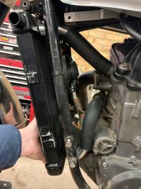
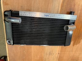
New idea for the radiator! I got a Suzuki GSF400 radiator and cut all the tabs off, and turned it sideways, and offered it up. It's the same area as the 690 radiator, so it should work. Here I've mocked up some hoses, and they fit pretty well. The upper hose fits between the frame cross members, and the bottom one tucks in front of the starter and behind the engine mount. The radiator will have to have some holes welded up, new pipes welded on, a filler neck welded on, and a temp sensor bung welded in. I'll mock it up and give it to someone else to weld.
Attachments
goodoltup
Been Around the Block
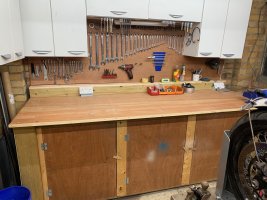
Another quick one: I painted my bench with some blue latex paint to keep the oil from seeping in, and never liked how it looked. Things got worse when after a few years I added another coat, which started to flake off. I tried to strip it but it turned into a gooey mess, so I took the top off the bench and flipped it over. Much happier with how this looks, plus no blue paint flakes sticking to everything.
Attachments
goodoltup
Been Around the Block
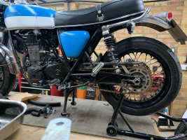
I had originally wanted to build this bike with 18" wheels front and rear, and ended up compromising by using the KTM wheels because it was easier and faster. I think they look good now, but the rear wheel always seemed a little too small for the fender, especially because the swingarm is almost 60mm longer than stock. Also the rim size in the rear holds a 160 tyre, which is a little too sporty for the application.
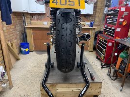
I like the look of the Pirelli Phantom sportscomp tyres, but they are not available in all sizes. I bought a 150 section Phantom rear tyre on eBay part used, and had it installed to see how it looks. The taller profile (70) makes it look a lot bigger. It's a much more appropriate tyre for the bike, I think. When the bike is torn down for final beadblast/paint etc I will put on two brand new Phantoms.
I like the look of the Pirelli Phantom sportscomp tyres, but they are not available in all sizes. I bought a 150 section Phantom rear tyre on eBay part used, and had it installed to see how it looks. The taller profile (70) makes it look a lot bigger. It's a much more appropriate tyre for the bike, I think. When the bike is torn down for final beadblast/paint etc I will put on two brand new Phantoms.
Attachments
goodoltup
Been Around the Block
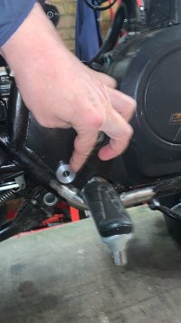
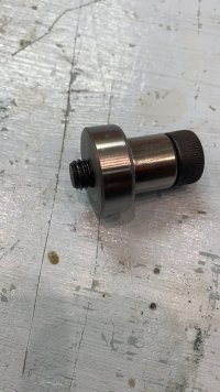
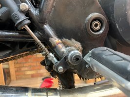
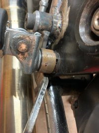
Rear brake pedal is shaping up. My neighbour bought a lathe and has been making parts for me, shown in the first picture is a washer that goes behind the shoulder bolt. Thank you Carl!
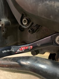
Still considering where to put the return spring, I may use a compression spring around the rod, acting on a tab on the frame. Last picture shows the footpeg, it now acts as a stop for the pedal. The 28mm diameter ring that the pedal stops on will be turned into an eccentric for pedal height adjustment.
Still considering where to put the return spring, I may use a compression spring around the rod, acting on a tab on the frame. Last picture shows the footpeg, it now acts as a stop for the pedal. The 28mm diameter ring that the pedal stops on will be turned into an eccentric for pedal height adjustment.
Attachments
goodoltup
Been Around the Block
goodoltup
Been Around the Block
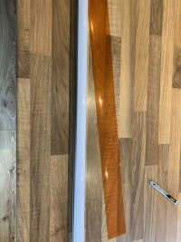
I cut and taped some CTO (colour temperature orange) gels to the LED lights and it made a huge difference. They are 50% CTO, and are supposed to take around 1500 off the temp. Now it looks more like the garage is lit by normal fluorescents and not HID lamps. There is some penalty to overall brightness but it not's much.
Attachments
Well deserved! It's a bloody beast of a buildI made the banner!
 I am keen to hear how the exhaust silencer goes... And what was the reason for the new radiator design? Overheating or looks? Or both?
 goodoltup
Been Around the Block
Hi Jadus, Thank you! Radiator is for looks only, the current setup works perfectly. And a bit of a challenge! The silencer went really well, I took it on a test ride last weekend and it was relatively quiet. The bike should really have a collector box and exausts on both sides to increase volume, maybe I'll do that in the future. All I have to do now is finish the radiator, do final fitment of all the cables and wires, and then it comes apart for blasting, paint, chrome, etc. I'm expecting about 1 year left based on my rate so far!Well deserved! It's a bloody beast of a build


