Awesome man, great job. Will almost be tough to ride it for a while and enjoy it, then pull it down for finishing and wait to ride it again! Haha
We noticed you are blocking ads. DO THE TON only works with community supporters. Most are active members of the site with small businesses. Please consider disabling your ad blocking tool and checking out the businesses that help keep our site up and free.
You are using an out of date browser. It may not display this or other websites correctly.
You should upgrade or use an alternative browser.
You should upgrade or use an alternative browser.
Project CB690 (KTM 690 engine in a CB550f frame)
- Thread starter goodoltup
- Start date
goodoltup
Been Around the Block
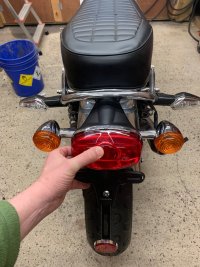
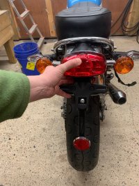
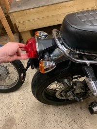
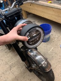
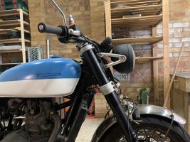
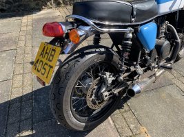
I got a tail light unit from a 2016 Thruxton, I love it. It will really clean up the lines of the bike and get rid of those ugly black blinkers. I will cut the tabs off of the grab rail, grind them down, and rechrome it. Also got an LED leadlight. I'll make new fork ears too, to move the headlight rearwards almost 40mm. The SV650 headlight ears that are on there now are almost 110mm long, which is unusually long.
Attachments
goodoltup
Been Around the Block
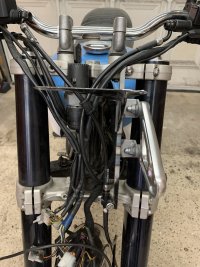
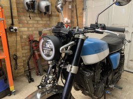
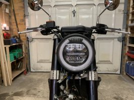
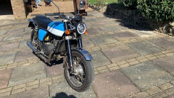
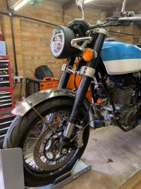
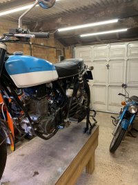
Reworked the headlight brackets to accept the Triumph ears and new headlight, and replaced the clutch and brake cables to fit the shorter bars. Very happy with how it all looks. The wiring didn't fit into the headlight shell initially, so I had to shorten some sub harnesses and replace some large connectors with smaller ones. Fits in very nicely now.
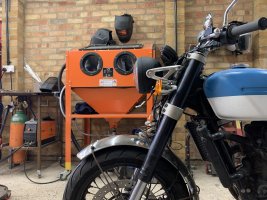
Also you can see my new bead blaster in the background.
Also you can see my new bead blaster in the background.
Attachments
Maritime
Over 10,000 Posts
pretty sure he wants to paint or powder the frame now that it's all sorted.Wait, full what?
goodoltup
Been Around the Block
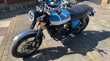
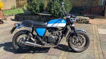
Thank you guys! Indeed, this whole thing is just a giant mockup before it gets torn down for bead blasting, painting, chroming, etc. All the manky fasteners will be replaced with swish button heads and stainless bits, it will get new tyres, everything will be cleaned and inspected and sorted. THEN, it will be done.
When it is 'done', I think I will ride it for a little bit, then consider any offers I may get on it. I'll be into it for about £10k. What do you think I could get for it?
When it is 'done', I think I will ride it for a little bit, then consider any offers I may get on it. I'll be into it for about £10k. What do you think I could get for it?
goodoltup
Been Around the Block
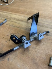
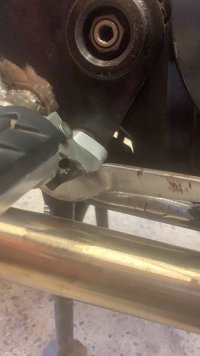
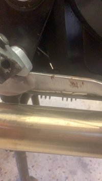
I haven't shown this much, but here is the eccentric brake pedal height adjust eccentric. It goes around the footpeg mount where the brake pedal would normally pivot around. You loosen the footpeg, adjust the eccentric, then tighten back up again. Not necessary, but thought it would be cool.
Attachments
goodoltup
Been Around the Block
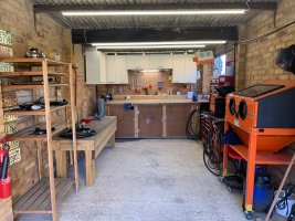
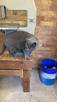
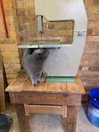
Current view of the workshop. I got an Inca Euro 260 bandsaw for £188, it is in perfect condition with all the extra bits like t-square, fence, beltsander attachments, manual and documents, etc. Well pleased. Ernie has inspected it and deemed it fit for service.
Attachments
goodoltup
Been Around the Block
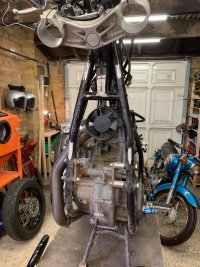
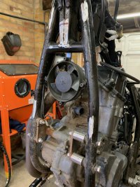
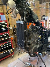
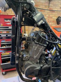
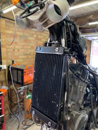
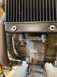
Back to the radiator again. Here the radiator is removed and the hoses mocked up. I removed both wheels and tilted the bike up for easier access to the area.
My aluminium welding is awful, and this is not the project to practice on. I think I will take the radiator I got and mock it up, tack it together, and use the radiator as a tool to show a professional radiator fabricator what I need. The prices are not too bad, £450 for a full custom radiator.
My aluminium welding is awful, and this is not the project to practice on. I think I will take the radiator I got and mock it up, tack it together, and use the radiator as a tool to show a professional radiator fabricator what I need. The prices are not too bad, £450 for a full custom radiator.
Attachments
goodoltup
Been Around the Block
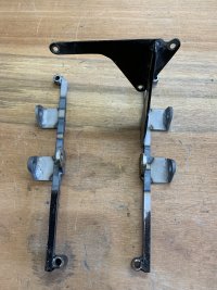
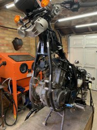
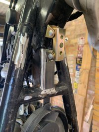
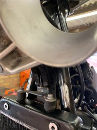
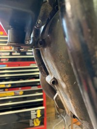
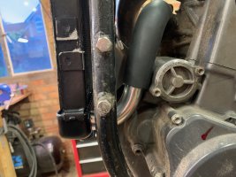
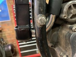
Bottom support done. This actually started as a top support but I measured wrong and it was too short, so it was repurposed into the bottom support. I decided to mount it to an engine bolt since it was convienent and it only needs to keep it from moving left and right. It is plenty secure.
Attachments
goodoltup
Been Around the Block
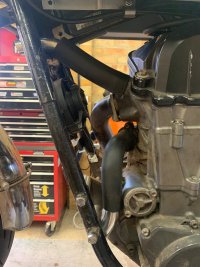
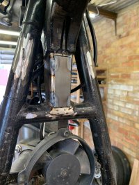
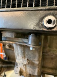
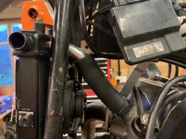
More radiator inlet and outlet mockup pictures. In the 3rd picture you can see my blood on the case cover, this was the result of essentially punching my vice. I was hacksawing through some aluminium and on the last stroke the metal gave way and my hand and hacksaw went right into the vice, bending back my index fingernail. It's not as bad as it sounds! Will be more careful in the future, however this is not the first time I've punched my vice and knowing me it won't be the last.
Next I will tack on the tubes to the radiator and do some more fitment trials.
Next I will tack on the tubes to the radiator and do some more fitment trials.
Attachments
goodoltup
Been Around the Block
Yeah I've given it the sweat, just need to round it out with some tears!Blooding the crankcase. Rite of passage!
goodoltup
Been Around the Block
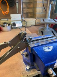
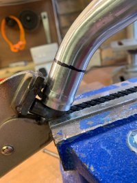
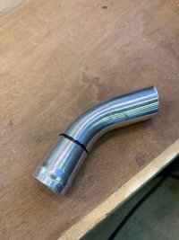
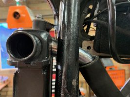
So I may as well have a go at welding this radiator myself, because if it works it works! With that in mind I made some modifications to my home made tubing beader and tried it out. It was very successful. The tubing diameter is 25mm, and the bead can be made to almost any diameter. I chose around 26.5mm for one hose and 27.5mm for the other hose. Being able to control the bead diameter was really useful for that, because 26.5mm felt way too loose in the bigger pipe, and vice versa.