Hey everyone,
I thought I would start to share my project now that I've passed the moment of no return. First a little background. About 6 years back I was getting tired of my current career as an auto mechanic and decided to go back to school for mechanical engineering. I have since completed my degree and working in the aerospace industry. I have always been a motorcycle enthusiast, but I have not had a bike since I made the decision to return to school. In my past I have built many bikes and have missed it greatly, so its finally time to start building again.
The bike:
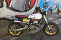
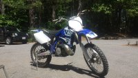
I had to sell all my bikes when returning to school other then my 2002 YZ250 motocross bike. Why didn’t I sell it? Because I would get nothing for it, and I had too much time invested into it. It was a 2002, but I gone through it several times including a full engine rebuilds, KYB SSS suspension swap, reduced offset triple clamps from a 2014 yz450, and the best part I had a street legal title for it.

The Plan:
While at my university I was a part of the Formula SAE competition and had built a small race car for my capstone design project. I guess they were doing some shop cleaning and I was lucky enough to be able to purchase one of their used engines, a 2015 Yamaha WR450f engine. I was at the school when they were using this engine, so I know that it was purchased new and has very low hours. So, after acquiring this engine I got the bad idea to combine my street legal YZ250 frame with the WR450 engine.
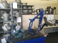
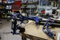
To be honest throughout my education and my current career I have become so use to creating designs and then running some form of analysis to validate the design before even creating a prototype. Obviously, there is nothing wrong with this mentality, but I feel like I need to get back to my roots and just say what the hell and chop a perfectly good frame in half before knowing it will work. Well, I couldn’t completely chop it up before checking a few things.
First step was to try to make a somewhat accurate CAD model of the frame so I could see what the engine would look like in the frame. I would have skipped this step, but the engine also came with a 3D scan file so how could I.

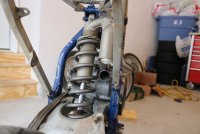
I was able to bring the frame into my work and use the FARO arm, a portable CMM, to measure all the critical points of the frame. I wish I had a 3D scanner, but only could record the center points of features such as motor mount bolts, suspension linkage bolts, sub frame attachment bolts, etc. The recorded measurements were imported into my CAD model, which resulted in this.

From there I started to model the frame. I had to make several dimensional assumptions based on traced photos of the frame, but for the what I was using it for it would be fine.

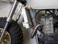
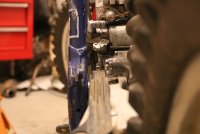
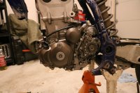
The rear engine mount, the one through the swingarm, was the same for both the YZ250 engine and WR450 engine. This made the swap somewhat easier because I did not need to worry about the chain alignment. However, you can see this engine was not going to fit into the frame.


To fix this I modeled new frame tubes to clear the engine and give some extra room for adjusting the engine angle.


I thought I would start to share my project now that I've passed the moment of no return. First a little background. About 6 years back I was getting tired of my current career as an auto mechanic and decided to go back to school for mechanical engineering. I have since completed my degree and working in the aerospace industry. I have always been a motorcycle enthusiast, but I have not had a bike since I made the decision to return to school. In my past I have built many bikes and have missed it greatly, so its finally time to start building again.
The bike:
I had to sell all my bikes when returning to school other then my 2002 YZ250 motocross bike. Why didn’t I sell it? Because I would get nothing for it, and I had too much time invested into it. It was a 2002, but I gone through it several times including a full engine rebuilds, KYB SSS suspension swap, reduced offset triple clamps from a 2014 yz450, and the best part I had a street legal title for it.
The Plan:
While at my university I was a part of the Formula SAE competition and had built a small race car for my capstone design project. I guess they were doing some shop cleaning and I was lucky enough to be able to purchase one of their used engines, a 2015 Yamaha WR450f engine. I was at the school when they were using this engine, so I know that it was purchased new and has very low hours. So, after acquiring this engine I got the bad idea to combine my street legal YZ250 frame with the WR450 engine.
To be honest throughout my education and my current career I have become so use to creating designs and then running some form of analysis to validate the design before even creating a prototype. Obviously, there is nothing wrong with this mentality, but I feel like I need to get back to my roots and just say what the hell and chop a perfectly good frame in half before knowing it will work. Well, I couldn’t completely chop it up before checking a few things.
First step was to try to make a somewhat accurate CAD model of the frame so I could see what the engine would look like in the frame. I would have skipped this step, but the engine also came with a 3D scan file so how could I.
I was able to bring the frame into my work and use the FARO arm, a portable CMM, to measure all the critical points of the frame. I wish I had a 3D scanner, but only could record the center points of features such as motor mount bolts, suspension linkage bolts, sub frame attachment bolts, etc. The recorded measurements were imported into my CAD model, which resulted in this.
From there I started to model the frame. I had to make several dimensional assumptions based on traced photos of the frame, but for the what I was using it for it would be fine.
The rear engine mount, the one through the swingarm, was the same for both the YZ250 engine and WR450 engine. This made the swap somewhat easier because I did not need to worry about the chain alignment. However, you can see this engine was not going to fit into the frame.
To fix this I modeled new frame tubes to clear the engine and give some extra room for adjusting the engine angle.
Attachments
Last edited:
")