cb360 left-hand switch wiring question

scottyhypnotic

New Member
I got some aftermarket switches from Dime City, and for the most part the wiring makes sense.

What I'm confused about is the "PL", "PR", and possibly "W" wires.


I'm thinking the Gray wire on the switches (T/S Main/F.Relay) goes to the "W" on the bike, possibly.

But what to do with the orange/white (PL), and blue/white (PR) wires?

I've attached the big wiring diagram, a view of the switch part, and the back of the box for my new switches.
 

Attachments

  • Honda color Schematic Late Model large.jpg
    Honda color Schematic Late Model large.jpg
    959.4 KB · Views: 3,636
  • IMG_0840.JPG
    IMG_0840.JPG
    124.2 KB · Views: 1,574
  • IMG_0869.JPG
    IMG_0869.JPG
    112.2 KB · Views: 1,201
"PL" and "PR" are your rear turn signals. "P" is for passing. Orange/white and orange/blue are rear turn signal wires. They go with the orange and blue wires, which are your front turn signals. They grey wire goes to your turn signal relay. "W" on the switch diagram is for Winker. Just make sure you're not confusing the "W" label on the switch diagram with a white wire, which is also labeled "W" in the diagram.
 
On this particular model, the blue/white and orange/white are for the front running lights. I usually cap those wires off and skip them.
 
Hmmm. So i'm a bit confused by the two posts.

I figured "P" was for parking.... which sounds more like Sonreir's answer. And I'd lean towards not hooking them up in that case.

Deviant, I think you're saying that without hooking them up I'd have no rear turn signals?

Would anybody else like to weigh in?
 
Hmmm. Having some troubles with those turn signals still...

I've wired everything up and headlight and horn work. Turn signals, not so much.

Here's what I've got:

Honda: Switches:
White White
Dark Blue Dark Blue
Yellow/Black Blue/White
Light Blue Light Blue
Orange Orange
Light Green Light Green
--- Black
--- Green/Red
--- Blue/White
Orange/White ---
Blue/White ---
Grey Extra Wire Grey
Bolt someplace Extra Wire Black (Seemed weird to me but its the only way the horn would work)


Any ideas... do the turn signals need some separate ground, or does capping off those PL and PR cause the issue?


I've attached the diagrams and switch colour/function guide below.
 

Attachments

  • IMG_0840.JPG
    IMG_0840.JPG
    124.2 KB · Views: 1,090
  • Honda color Schematic Late Model large.jpg
    Honda color Schematic Late Model large.jpg
    959.4 KB · Views: 773
  • IMG_0869.JPG
    IMG_0869.JPG
    112.2 KB · Views: 1,106
From your new control to the harness:

Sky Blue -> Light Blue
Orange -> Orange
Gray -> Gray

Unless you have problems with the flasher or the turn signals, themselves, that should be all you need.
 
Thats definitely what I have. And they don't work.

They did prior to this with my old switches. So I figure the signals and relay were fine since they were a couple of hours ago. Hmmm...

I can't imagine whats up.


Also... what are the wires coming out of the original clutch perch and disappearing into my headlight? I'd assume they're a clutch switch so the bike won't start in gear? I've replaced my switches as well as my clutch perch. I am supposed to be wiring something else here from my new clutch perch? I don't see any form of switch or anything? Or can I pull the clutch switch wires coming from the old assembly that disappear into the headlight, and not worry about having some sort of replacement for it. I'm a little confused by that. Is that what the green/white, and green/red wires are for for my new switch. And what would they do with a new lever and perch that don't seem to have a switch?
 
Let's worry about that other stuff once we sort out the signals. One thing at a time or you'll end up going crazy. ;D

OK. So under the seat area you should have your flasher relay. Verify that you have a black wire going into the positive terminal and a gray wire coming out the other side.
 
Ah! Good advice all around...

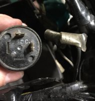
So it looks like I did knock connections off of what I assume is the relay. There's a pic below. Is that it?

I can't really tell whats positive and whats negative as one is labeled "L" and one is an "X". I tried connecting the grey and black wires both ways and still no signals.


Also while I was down there I saw a bundle of Yellow, black, Green, and green/yellow wires. And the Green had a connector going to nowhere. Does that make a difference here?
 

Attachments

  • IMG_0879.JPG
    IMG_0879.JPG
    1 MB · Views: 373
  • IMG_0881.JPG
    IMG_0881.JPG
    980.1 KB · Views: 530
Green is optional, depending on the flasher.

X should be the black wire and the L is for the gray.
 
Okay. I hooked all that up that way, and no dice.

Are my two black wires an issue? One says ground, in general, and the other "Extra Black" seems to be ground/flasher relay.

That ground/flasher relay one needs to be used for the horn to work, and the other ground hasn't been making much difference
 
Probably not. Those wires shouldn't come into play for the turn signals.

OK... so the black wire going into the flasher relay: Any voltage on it when you check with a multimeter?
 
I don't have one! I'm gonna hop out now and get one.

I'm new to this. How am I testing it? Touching both positive and negative prongs to the black wire?

Also, if the relay is the problem, would this one work as a replacement?

http://www.canadiantire.ca/en/pdp/pilot-automotive-40-amp-relay-0203760p.html#srp


I really appreciate your help on all of this, btw. I've checked out your website too and I have no doubts that I'll hit up Sparck for wiring needs in the future.
 
To measure voltage, the red probe on the thing you think has power and the black probe to ground (any bare metal on the bike or the battery negative terminal).

And you'll want to a flasher relay. That is an automotive (aka four/five pin) relay.
 
Back
Top Bottom