
Hi everyone,
It's time to get my CB up and running so that I can tune it and have it road ready in a month or two. Since I'll be riding my other bike mostly, I'm going to start with a minimum wiring diagram, and slowly add the blinker/horn/etc. When everything works properly I'll do a vintage connections re-wire in the winter.
So, I'm using this diagram and I'm having a little trouble:
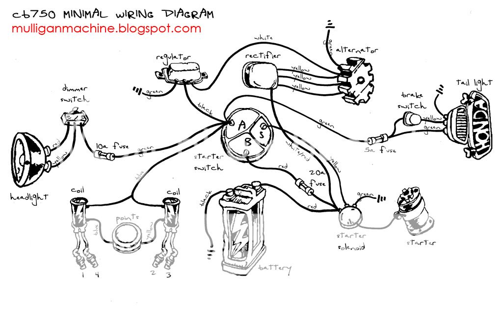
I understand this is mostly trial and error but I really don't want to fry anything. Therefore I'm asking for some help in identifying a couple of wires on the Starter Solenoid and the Key switch, both of which are stock.
The diagram above shows only three terminals to attach wires to the key switch: a, b, and s.
They key switch pictured below has four, however: IG (Black) Batt (Red) TL2 (Brown, and there's two soldered connections on it for reasons unknown to me) and TL1 (brown with white stripe). What do these designations mean? And where should the stock connecting wires go in relation to the minimum diagram?

I'm also confused about the starter solenoid.

The large black wire connected to the SS on the right of the photo I've taken above is connected to the starter.The black wire that is soldered onto the lower middle part of the solenoid is connected to ground. Notice that there is a yellow wire peeking out at the top of the solenoid which then is run with the black ground wire. That wire has a red stripe and I'm not sure where it goes.
I'm also stuck on two wires that are connected to the same terminal as the large battery wire: a black one, and another small red one (with the spade connector in the below picture).

I believe the black one (with some form of aftermarket blue crimp terminal on there) should actually be (or is, and too dark to tell) blue.
If you guys could help me out and let me know what's what, I would be supper appreciative. I'll be happy to be more specific if anyone needs.
Thanks!
It's time to get my CB up and running so that I can tune it and have it road ready in a month or two. Since I'll be riding my other bike mostly, I'm going to start with a minimum wiring diagram, and slowly add the blinker/horn/etc. When everything works properly I'll do a vintage connections re-wire in the winter.
So, I'm using this diagram and I'm having a little trouble:
I understand this is mostly trial and error but I really don't want to fry anything. Therefore I'm asking for some help in identifying a couple of wires on the Starter Solenoid and the Key switch, both of which are stock.
The diagram above shows only three terminals to attach wires to the key switch: a, b, and s.
They key switch pictured below has four, however: IG (Black) Batt (Red) TL2 (Brown, and there's two soldered connections on it for reasons unknown to me) and TL1 (brown with white stripe). What do these designations mean? And where should the stock connecting wires go in relation to the minimum diagram?
I'm also confused about the starter solenoid.
The large black wire connected to the SS on the right of the photo I've taken above is connected to the starter.The black wire that is soldered onto the lower middle part of the solenoid is connected to ground. Notice that there is a yellow wire peeking out at the top of the solenoid which then is run with the black ground wire. That wire has a red stripe and I'm not sure where it goes.
I'm also stuck on two wires that are connected to the same terminal as the large battery wire: a black one, and another small red one (with the spade connector in the below picture).
I believe the black one (with some form of aftermarket blue crimp terminal on there) should actually be (or is, and too dark to tell) blue.
If you guys could help me out and let me know what's what, I would be supper appreciative. I'll be happy to be more specific if anyone needs.
Thanks!


