Possible, but unlikely. There's only one ground in the DOHC charging system and it's fairly low current. Even a shoddy ground is likely to be OK.
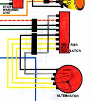
Attached is a picture of the DOHC charging system. As you can see, almost all of the wires are running between the alternator and the R/R, so that's likely where the problem exists (either with the components or the wiring). The field coil gets power from the black wire (it's a pass-through from the other black wire going to the main harness) and then regulates power by varying resistance on the white return wire. Electricity generator by the alternator comes back through the R/R on the three yellow wires. They're rectified (changed from AC power to DC power) and then it exits the charging system out through the red wire to the solenoid, where it's connected to main power for the rest of the bike. The remaining green wire from the R/R is present only for the voltage sensor (which is also run from the black wire coming into the unit). Unlike permanent magnet regulator/rectifiers, the ground wire isn't a major concern because so little power passes through it.
Anyway... here is how I would proceed with testing if the bike were in my shop:
1.) Unplug the regulator/rectifier and remove the alternator cover. Measure resistance between the white and black wire from the rotor. We're looking for about 3.5 to 5.0 Ohms. Lower or higher is both cause for concern and the further we drift the more concern it should cause. If we have a good reading, then measure between the black wire and ground. We should not be able to get any reading at all (aka Open Line). If the resistance checks are OK, run a jumper from the wires to the battery. Black to positive and white to negative. Make sure a wrench will stick to the rotor. If we've failed at this step, we have a problem with the rotor, the brushes, or the wiring. Use a multimeter to read resistance between key points in the circuit to identify the point of failure.
2.) Replace the alternator cover and repeat the resistance tests (including test to ground) from step one. They should remain the same.
3.) Measure resistance between each of the three yellow wires and then from one of the yellow wires and ground. We should get about .5 Ohms on each pair of yellow wires (three separate measurements) and Open Line when measuring from a yellow wire to ground. If we are unable to get a low enough resistance reading, then we might have corroded terminals or bad wires. An Open Line reading on any of the yellow-to-yellow measurements is a failure in the wiring or the stator. Open Line between any yellow and ground is a failure of the stator as well.
4.) Moving over to the other R/R plug (red, green, and black), measure resistance from the red wire to the battery positive terminal. We should have under an Ohm and lower is better. Turn the ignition key to the on position and measure between the black wire and the battery positive terminal. Also looking for under an Ohm on this one. Turn the key back off and measure between the green wire and the battery negative terminal. Also looking for under an Ohm on this measurement. Any failures here are probably an issue with wiring or terminals. This would be fairly easy to correct and we can run through the solution if this is where the problem lies.
5.) Finally, testing of the R/R. If your meter has the ability to do so, perform a diode check on each yellow wire and the red wire on the unit. Also do a resistance check between both black wires. Any other, more complicated, tests will require an adjustable power supply. If you have one, please let me know and I can cover those tests as well.
6.) Assuming all these tests pan out, your system should be charging. Any failure to achieve proper system voltage might still be related to the R/R, but it possibly a short within the system. At this point, it's usually easy to just replace the wiring (at least for me) than it would be to track down the possible short, but I can run you through that process as well, assuming we haven't already found the issue by now.