69 CB350 - Modern Suzuki Front | Ducati Rear - Cognito Moto

teazer said:
Unfortunately that box section/engine mount is not as rigid as it might appear. Some years ago I gave myself a nasty fright following another guy on a CB77 racer. the back end was flapping about in the breeze.

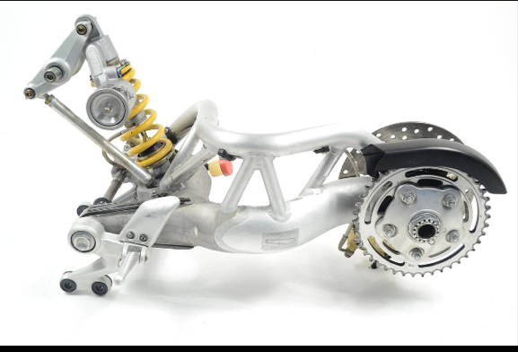
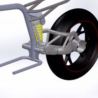
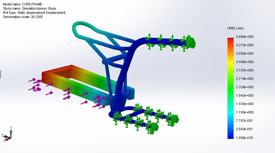
Unless teh holes are reamed and super tight fitting mounting bolts used, the frame walks around the motor mounts with a stock bend swingarm and will act like a spring with a more rigid swingarm and grippier tire. That center section is too narrow to resist the twisting forces effectively. The wider the support, teh more resistance to twist, so adding tubes outside the swingarm pivots is a good idea.

Where is a go pro when you need one!


www.CognitoMoto.com
 
SpeedBump said:
The support removed on the frame supported rider and suspension. Now all of the suspension load goes back into the core frame.


www.CognitoMoto.com
true all the loads go to the center and also into attempting to bend the pivot bolt from both ends
 
xb33bsa said:
true all the loads go to the center and also into attempting to bend the pivot bolt from both ends

This swingarm actually has a 20mm swingarm shaft. That shaft is pressed into the swingarm and by design moves with the swingarm.

epama4ur.jpg


www.CognitoMoto.com
 
xb33bsa said:
but you must have a very substantial , wide center section to support it

That center tube supporting the swing arm is 7" long. I can not go wider than the swingarm allows. The Ducati swing arm bolts almost identical to the stock cb350 swingarm. The inside is the frame mounting (pivot point) and the outsides mounts keep the shaft from walking.


www.CognitoMoto.com
 
Hopefully these images help clarify some things.
 

Attachments

  • render.jpg
    render.jpg
    103.4 KB · Views: 385
  • exploded.jpg
    exploded.jpg
    89.7 KB · Views: 394
xb33bsa said:
good luck that may work the cb350 frame is what i thought we were taliking about

Haha! We are redoing most of the frame and replacing sheetmetal with tube.


www.CognitoMoto.com
 
I would use just the single caliper and rotor up front. Save a lot of weight and rotating weight.
In the rear I would run a near vertical tube from the sub-frame down to the horizontal swingarm support tube. Vintage XS650 Yams. (racing) have a similar town tube problem and can crack the frame just below the big curve. The bike already looks cool.
Cheers, 50gary
 
SpeedBump said:
That center tube supporting the swing arm is 7" long. I can not go wider than the swingarm allows. The Ducati swing arm bolts almost identical to the stock cb350 swingarm. The inside is the frame mounting (pivot point) and the outsides mounts keep the shaft from walking.

That raises two issues. It suggests that the Ducati frame is a single tube which it isn't, and it raises the real issue that teh Duc ties teh ends to something to stop them moving.

The forces that will tear the frame are not simple straight up and down hitting a bump, but cornering when laid over at an angle. In that situation, the forces are sideways on the middle of the frame trying to push the bike out against the friction between tire and road.

The easy way to think of it is to imaging clamping the motor and the center of the frame in a jig and apply a sideways force to the bottom of the rear wheel. The wheel will tend to twist vertically and the center frame tube will tend to just rotate and act like a big spring. That is exactly how our old Triumphs reacted - like a ratchet going around corners. It would wind up until the force in the frame tube was greater than the friction at the wheel and then it would skip sideways and repeat . With a stiffer swingarm and stickier rubber, side forces will resolve through the frame.

Fortunately not a whole lot of power to deal with but still enough to cause a problem going round corners potentially. I'd like to see FEA showing stresses and deflection in that frame.
 
It's been a while since my last post but we've made some progress on the frame. It's still unfinished but I wanted to give you guys some pics to look at.
 

Attachments

  • welding.jpg
    welding.jpg
    121.3 KB · Views: 380
  • frame-welding.jpg
    frame-welding.jpg
    184.4 KB · Views: 501
  • mockup.jpg
    mockup.jpg
    169.1 KB · Views: 511
  • mockup-2.jpg
    mockup-2.jpg
    148.2 KB · Views: 501
That's what I was suggesting in reply #28. I would also drill a large diameter hole in each of the two lower plate gussets. Eventually cradle frames always end up or tend towards a version of the Featherbed. Single tube backbone frames are an economic "solution" IMO.
Cheers, 50gary
 
50gary said:
That's what I was suggesting in reply #28. I would also drill a large diameter hole in each of the two lower plate gussets. Eventually cradle frames always end up or tend towards a version of the Featherbed. Single tube backbone frames are an economic "solution" IMO.
Cheers, 50gary


www.CognitoMoto.com
 
How did you run that simulation? Is it a multi-body part? Any chance you could shoot me the file(s)? The whole SolidWorks simulation suite still baffles me. :-X
 
Back
Top Bottom