Adding DC to Scooter

firebane

braaaaaaaaaaap
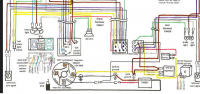
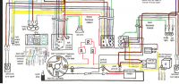
I know that we have a couple of talented people in here that know a thing or two about electrical. Right now I am looking into adding a 12v circuit to a scooter with only AC so that lights and horn work off of 12v. I have included 2 diagrams for reference and from I can see as long as I add a rectifier and regulator off the yellow wire from the magneto I can then took it up to a battery to provide said power?

Any issues seen with this?
 

Attachments

  • before.png
    before.png
    636.6 KB · Views: 175
  • after.png
    after.png
    621.4 KB · Views: 169
So upon further reading it looks like I could use a Kohler R/R combo unit.

Yellow lead goes into the R/R unit with the B+ going out to the battery. Run a fuse inline and run a power lead to the other side of the yellow like above.

Would probably install a switch for the wiring as well to allow the lights system to be turned off and on when the bike is off.
 
you got it. AC is tricky stuff if you tried to run the lights or anything else.
(figuring out voltage's and amperage's requires imaginary numbers, and its ONLY for time t=0)
 
Keiff Hardcore said:
you got it. AC is tricky stuff if you tried to run the lights or anything else.
(figuring out voltage's and amperage's requires imaginary numbers, and its ONLY for time t=0)

Yeah AC lights and horns are brighter or louder based off of RPM. I want something that will be constant so needign 12v DC is the best route.

There won't be any issues only using 1 of the 2 poles for AC on the R/R by Kohler?
 
if its a 3 pole than i wouldn’t think so.

the idea though is to (i believe) have both the pos and neg wire from the source and the 3rd pole is grounded.
 
your first diagram shows an AC regulator for 12V.

I suspect at idle, you do not generate enough electric to reach 12V (either AC or DC). those type regulators only limit the voltage, they do not boost it if you are only, say 10V, at idle.

So you can convert to 12V DC, but still have dim lights at idle and low RPM, like you do now.

Also, no imaginary numbers needed to calculate Amps and Volts and resistance.. Ohms Law works fine.
Volts = Amps * Resistance
or
Amps = Volts/Resistance
or Resistance = Volts/Amps

Or
V=Volts
I=Amps
R= REsistance

So
V=IR
I=V/R
R=V/I

You always need 2 of the values to calculate the third.
 
mydlyfkryzis said:
your first diagram shows an AC regulator for 12V.

I suspect at idle, you do not generate enough electric to reach 12V (either AC or DC). those type regulators only limit the voltage, they do not boost it if you are only, say 10V, at idle.

So you can convert to 12V DC, but still have dim lights at idle and low RPM, like you do now.

Also, no imaginary numbers needed to calculate Amps and Volts and resistance.. Ohms Law works fine.
Volts = Amps * Resistance
or
Amps = Volts/Resistance
or Resistance = Volts/Amps

Or
V=Volts
I=Amps
R= REsistance

So
V=IR
I=V/R
R=V/I

You always need 2 of the values to calculate the third.

LOL that made my head hurt.

Explain to me why adding a r/r unit inline would not give 12v for? People have been adding 12v to chinese scooters for a long time.

Or do you perhaps have a better idea of how to go about doing this?
 
You are reading too much into that.

1. You have 12V AC already and a regulator.

2. You can definitely add the r/r for 12V dc.

The problem is the alternator will still not put out anymore current....the battery will provide some voltage when the engine is at low RPM, but you probably won't keep the battery fully charged...

Not as big an issue as you have a magneto, and the bike will always run, but I suspect the likes will dim at idle anyway...That was my point....

Batteries are not the source of electric, just a storage of it. you need excess capacity to have some to store. Those systems are anemic, and will only perform marginally better with a battery. My point being a bit of work for a relatively small gain.

It isn't whether it can be done or not, but should you do it?

I actually say do it, it will be a good learning experience. That has value....

What is the amp or watt output from the scooters alternator? We can easily calculate the current available to run the lights and charge the battery...
 
Your R/R isn't wired correctly. You'll need each of the alternator wires to connect to the R/R (there are two AC connectors on a Kohler and both need to be connected to their own wire and not wired inline).

Second, you left the AC regulator in place. That needs to be removed.

After that, you need to replace all of your AC component with DC components.
 
What he can do is leave the Ac regulator in place, just add a rectifier after the regulator....12V A/C will be close to 12V dc after the rectifier.

But I agree with you, better to go all DC....The headlight will be ok, but the horn and signals may not.

Still, those alternators have marginal output, less than a cb350...The headlight is likely a 25 or 35W , and the system can't keep up with that at lower RPM....
 
Sonreir said:
Your R/R isn't wired correctly. You'll need each of the alternator wires to connect to the R/R (there are two AC connectors on a Kohler and both need to be connected to their own wire and not wired inline).

Second, you left the AC regulator in place. That needs to be removed.

After that, you need to replace all of your AC component with DC components.

But there is only a single wire coming off the alternator. So would I need a r/r unit with only 1 ac pole? The other lead off the alternator goes to the CDI for the spark plug.

@ mydlyf, the alternator puts out 12v @ 80w
 
the "other" wire is ground if the schematic reads right. the lighting coil is grounded on the other end.

80 watts is about 6 amps. A 35w headlight is 3 amps... The output is RPM related, so the rating is probably at close to max RPM. At idle, if you were putting out 3 amps, the light would stay bright....

Just to let you know what you are dealing with.

A small battery needs to be charged at about 1 amp. So you need a good 4.5 amps or so to charge the battery while headlight and tailight are on, to charge the battery....You probably need about 50-60% RPM to get there.

So idle you would have battery voltage (12 V), at 60% our so RPM, you would have 13.6-14 Volts, and full RPM, about 14.5 volts, using a standard voltage regulator.

The battery does not charge until the alternator voltage is above 12.6 to 12.7 volts. Most Battery charging systems maintain about 14.4 to get optimum charging.
 
This whole AC to DC thing is confusing lol and I'm getting information that is confusing as well lol and I feel that people are trying to over complicate this.

My understanding is the magneto is a single phase as it only has 1 yellow wire. The other wire is the ignition wire which goes to the CDI and to the kill switch. The third wire just grounds out.

The single yellow wire is fed into the 12v AC regulator which then sends power out to the electrical system.

So this is why I feel that I could just remove the AC regulator from the scenario install something like the Kohler unit and run a battery and a 12v system.
 
The Kohler unit has 3 connections. The case needs to be grounded.

The three connections are AC, Batt +, AC and ground the case.

60de.jpg


the problem is your AC and Batt - (ground) are shared, and the case of the regulator gets grounded. that may be an issue.

But they regulators are cheap, the worst that may happen is you smoke the regulator.

You will need to ground one of the AC tabs on the regulator to complete the AC circuit. that's where the problem might be.....

Try it and let us know how it works... If it does or doesn't, I learned something too.
 
firebane said:
This whole AC to DC thing is confusing lol and I'm getting information that is confusing as well lol and I feel that people are trying to over complicate this.

My understanding is the magneto is a single phase as it only has 1 yellow wire. The other wire is the ignition wire which goes to the CDI and to the kill switch. The third wire just grounds out.

The single yellow wire is fed into the 12v AC regulator which then sends power out to the electrical system.

So this is why I feel that I could just remove the AC regulator from the scenario install something like the Kohler unit and run a battery and a 12v system.

Single phase means two wires from the alternator. The yellow wire is one half of the circuit and the black wire is the other. AC means alternating current (of course), so the polarity is rapidly changing. Sometimes ground is positive and sometimes ground is negative.

To rectify the current to DC, you need to ensure that ground is always negative. This is done by taking the ground wire from the AC alternator and hooking that up to the rectifier along with the yellow one. The internal structure of the rectifier means that it doesn't matter if the black wire or the yellow wire is positive, the output will always be positive (and therefore ground can always be negative).

And yes, you can (and should) remove the AC regulator when you make the change to DC.
 
Sonreir said:
Single phase means two wires from the alternator. The yellow wire is one half of the circuit and the black wire is the other. AC means alternating current (of course), so the polarity is rapidly changing. Sometimes ground is positive and sometimes ground is negative.

To rectify the current to DC, you need to ensure that ground is always negative. This is done by taking the ground wire from the AC alternator and hooking that up to the rectifier along with the yellow one. The internal structure of the rectifier means that it doesn't matter if the black wire or the yellow wire is positive, the output will always be positive (and therefore ground can always be negative).

And yes, you can (and should) remove the AC regulator when you make the change to DC.

This makes sense!

Hook black and yellow up to ac inputs on kohler with bat going to obvious. Yank the ac regulator and then power up the electronics.

Thanks much appreciated.
 
Back
Top Bottom