Follow along with the video below to see how to install our site as a web app on your home screen.
Note: This feature currently requires accessing the site using the built-in Safari browser.
We noticed you are blocking ads. DO THE TON only works with community supporters. Most are active members of the site with small businesses. Please consider disabling your ad blocking tool and checking out the businesses that help keep our site up and free.
but the connectors weren't as pictured and they don't work with the CB350. I know DCC has some good stuff, but I'd like to
1) get something more in the range of $50 for a pair
2) keep the wiring fairly straightforward
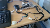
What was the issue with the connectors? Wire colors may be off but those should have the same wiring that the stock cb350 ones have (except for the starter button it looks like).
Yeah, definitely wrong terminals. I actually like latching terminals like those but you'd have to swap the terminals on your stock harness still and my assumption is they wouldn't be able to be routed through the handlebars like is stock. FWIW, you may want to look closer at the terminals within the latch. Are they bullet terminals or spade terminals? If bullet, check and see if each of the actual wire terminals can be separated from the latch. If spade, you're out of luck obviously. Even if they don't come out or are spade, it still is easy to put new, proper 3.5mm bullet terminals on each wire from the switches and fix what you already bought. I'd do that unless, of course, the seller just made a mistake and would be willing to do an exchange for the proper models.
I don't think you're going to get a better deal than $35 unless you buy used or you switch over to a single switch housing with most functions, like one of these (which I realize now doesn't have the starter button either):
You can buy new terminals from electronic suppliers. Look for 3.5 mm bullet terminals, which was stock on the cb350. They're a bit rarer but can be found. Perhaps try posting a WTB thread on here and maybe a member has a few extra they'd be willing to sell. Then, you basically cut the old ones off, strip 1/8" of wire to expose clean copper, then crimp the new terminal on.
If you think you are going to customize this bike in the future it may serve you well to buy a kit from Vintage Connections (http://www.vintageconnections.com/), a reputable supplier according to many members here, myself included. I bought one of their kits a few years ago that included a bunch of terminals and a really nice crimper. I've used it a lot since then on a number of different bikes. The kits don't come with the 3.5 mm terminals Honda used (instead they come with 4 mm) so you'd have to swap out both sides on your bike or buy extra 3.5mm terminals from them (they're like $5 for a 25 pack).
You could do either the switch side or the harness side. I'd be inclined to just do the switch side, remove the latches/spade terminals all together and replace with a bullet terminal on each wire (no latches necessary). Look at your stock switches and just emulate them. Then, the bike would be in stock form. If you wanted to use the latches then you would have to find a female latching box with female spade terminals that mated and lined up with the male terminals on on the switches you bought, then you would make sure each wire from the harness was placed in the slot in the new latch corresponding to the proper function. Sounds more difficult (and dirtier) than it is.
hahahha, cool. Well I just returned the switches a couple of days ago sadly. They thought they had shipped me an incorrect part because they didn't match up with the picture, but it turns out they just had changed out the part to have the new connectors (yay!), so they just had me return it. Looks like I'll be buying another set
ALRIGHT!!! Got the new set in and am going to pick up the kit you suggested. SO, my next question is: What do I need to know to make sure each wire is going to the correct place? Can/Should I just be tracing from within the switches, or should I get a diagram from the seller?
You should definitely get a diagram from the seller. If they can't provide one, check around eBay for one that looks exactly the same and see if a wiring diagram is posted in the Item Description. Most of these are knockoffs built in large quantity in China or Japan, so the same items are sold through a ton of vendors. One of them is bound to have it.
You should be able to purchase matching latching blocks with connectors at Eastern Beaver or Vintage Connections or other places. They are not expensive and if you buy a complete connector you can change the length of the harness to match your installation.
Mapping connections in a plug is easy. It requires 4 tools
1- Multimeter or test light and battery
2- Pen and paper to write things down
3- Methodical approach
4- Patience
A wiring diagram helps of course, but that's about all it takes with our old clunkers.
Sweet! SO, I already purchased the kit from Vintage Connections to swap out the ends that are on the switch side (going to bullet connections as opposed to latching). What would the process be to map out what connects where if I'm going with those connections?
Do you have a multimeter and/or test light? If no multimeter a test light can be rigged up fairly easily with an old 12v light bulb and some small lengths of wire (which would be your positive and ground). Positive wire goes to nub on the back of the light and the ground goes to the metal bulb housing.
Someone can chime in if this is incorrect, but I believe the process is pretty similar regardless of whether you use a multimeter or test light/battery. You need power coming into the controls, which is provided either by multimeter itself through one of its leads while in continuity test mode or directly by wire from a 12v battery's positive terminal. You will need to initially make a guess as to which is the hot wire coming in on your controls and hook that line up to your power source. Hopefully someone else will have a better way to identify it (on stock wiring it's a black wire). Then you can attach the other end of your multimeter or the positive of your test light (ground of test light should be grounded to something) to one of the wires and start flipping switches on the controls. When the switch that controls the wire you are testing matches, there will be continuity (multimeter will beep or test light will light up).
If I need to test for power, I use an old lamp and holder from an instrument (tacho or speedo) and lengthen the wires and fit alligator clips on the ends. In this case you connect one battery terminal to one side of the lamp. The other side of the lamp is one test probe. The lead from the other battery terminal is your second test probe.
What you are looking for are terminals that light the light when different switches are in the OFF and ON positions.
There are different ways to sequence it, but start with a diagram of all the pins. Start with all switches in the OFF position. Touch one probe to the first terminal in the switch block and the other to each other terminal one at a time. If any cause the bulb to light up, write that down.
Repeat by moving the first probe to the second terminal.lead and test all other connections. That will take less than 5 minutes.
Next, turn ONE switch to the ON/RUN/ other position and repeat the test to see which cause the lamp to light.
Repeat of each switch in the block and pretty soon you will know which wires belong to which switch. Just map it out one circuit at a time - methodically. It's takes less time to do it that to write it.
This site uses cookies to help personalise content, tailor your experience and to keep you logged in if you register.
By continuing to use this site, you are consenting to our use of cookies.