Bare bones wiring diagram?

timeconsuming

Foolish until proven intelligent.
Hey guys

I've been tearing things off my bike left and right and have come to the realization that there are really only a few things I want on my bike:

-kick start
-headlight hi/lo/off switch
-tail light + front & rear brake light switches

in other words:

-no electric start
-no signals
-no idiot lights (including no speedo & tach lights)
-no horn
-no kill switch (key is front and center, stock position on cb400f)

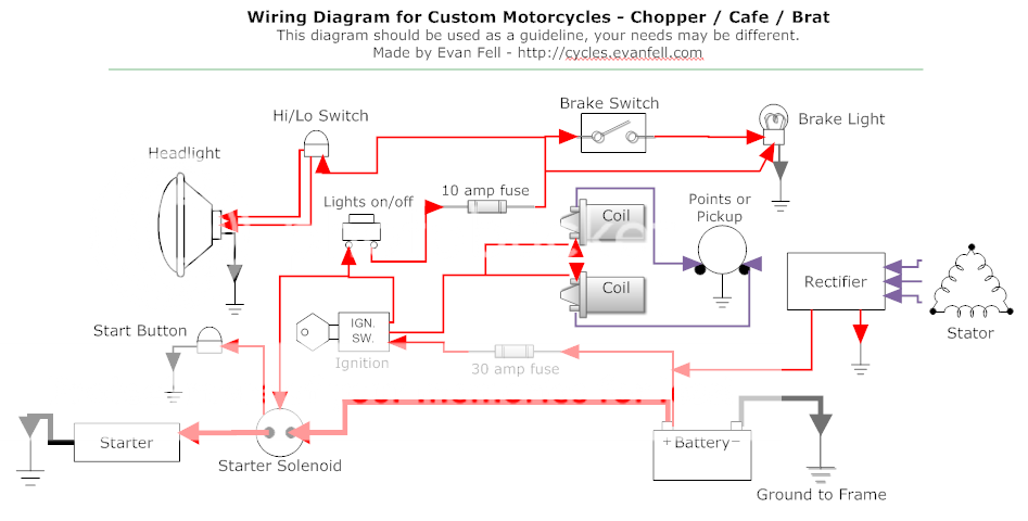
I've tried searching but have yet to find a truly bare bones wiring diagram to help me visualize just how little I'll need to keep my bike running daily with these small electrical components.

This is the closest I can find, and it's a great diagram:

index.php


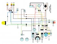
Especially when compared to my stock diagram:

CB400F-US-Wiring-Diagram.jpg


But I can't help but think someone's put together a bare minimum diagram that could help me out. Anyone able to point me in the right direction?
 
Check this one out

http://www.hondachopper.com/garage/simple_wiring_diagram/simple_wiring_diagram.html
 
Thanks guys, those are both helpful.

I'm curious how a battery would wire in without the starter/solenoid... would I simply remove the starter solenoid then route:

reg/rec (red/white wire) > + battery terminal > fusebox (red wire) > ignition switch ?

Anyone have any photos/examples of this being done?
 
Custom_Motorcycle_Wiring_Diagram_by_Evan_Fell_zpsa8c6b0f9.png


Just remove the heavy red wire from the battery to the solenoid. Removing the solenoid is optional. If so, just disconnect all the wires at the solenoid. Cap off the small red wire from the ignition switch to the solenoid and you are good to go.

Another thing, the amperage rating on the fuses is way too high. 15 amp main is plenty. Lights only need 7. Unless you put heavier gauge wire on, the 16 ga wire is not able to handle 30 amps without melting. The fuses keep the wires from overheating. So a fuse shouldn't have a higher rating then the amp capability of the wire after the fuse. A 60 Watt head light is less than 5 amps draw. The other lights use less then the 2 amps remaining. This way, if you have a problem, the fuse blows rather then the wire melting.
 
The pink connections in the first diagram are just that - bullet connections. You can get vintage style bullet connections that are 1 to 1, 1 to 2, and 1 to 3 junctions.
 
mydlyfkryzis said:
Just remove the heavy red wire from the battery to the solenoid. Removing the solenoid is optional. If so, just disconnect all the wires at the solenoid. Cap off the small red wire from the ignition switch to the solenoid and you are good to go.

Another thing, the amperage rating on the fuses is way too high. 15 amp main is plenty. Lights only need 7. Unless you put heavier gauge wire on, the 16 ga wire is not able to handle 30 amps without melting. The fuses keep the wires from overheating. So a fuse shouldn't have a higher rating then the amp capability of the wire after the fuse. A 60 Watt head light is less than 5 amps draw. The other lights use less then the 2 amps remaining. This way, if you have a problem, the fuse blows rather then the wire melting.

Thanks for this info, I love learning the reasoning behind things rather than just being told to do something because it's right.

Also my bike currently runs 7 - 15 amp fuses so I was thinking of just keeping the box as is rather than running inline fuses.
 
Tim said:
The pink connections in the first diagram are just that - bullet connections. You can get vintage style bullet connections that are 1 to 1, 1 to 2, and 1 to 3 junctions.

I may be confused but whats the purpose of the two on the neutral light ground?
 
semaj4712 said:
I may be confused but whats the purpose of the two on the neutral light ground?

Well, one is between the idiot light and the harness, the other between the switch and the harness - that's my guess. The section of wire between the idiot light and the neutral ground is likely in a bundle of wires in a harness, so you need connections at both ends.
 
as Tim said, they are just connections. The neutral light is either in the gauge or in a "pod". There is a disconnect so you can remove the gauges without removing or cutting the wire.

On most Honda's, the neutral light switch is behind the sprocket cover. That wire joins the alternator wire and disconnects at the 4 wire connector just above the sprocket cover.

This way you can remove the side covers without removing the wire all the way up to the light.

Most of the electrical buts a re set up:

Light ---->connector<----------Wire harness--------->Connector<---Source

This way the chassis can have the harness installed, then add the rest of the elctrical devices as you assemble.

There are a LOT of connections on the bikes.
 
Not to thread jack, but can someone explain to me this portion of the first diagram...

I was using it as a template to map out my current setup to see how easy it would be to actually re-wire it...however this part confuses me...

My current setup
bikewirediagram.jpg


Why is the alternator rectifer and regulator wired like this...what is that blue part? and wire so many wires between the three?
bikewirediagram_inquestion.jpg
 
The blue thing is likely the headlight switch, some bikes with a balanced charging system put out more current with the headlight on.
 
Honda has a split alternator coil. 1/3 2/3 output. headlight off, 1/3 output. Headlight on, both engaged for full output. The headlight and other lights use most of the power on our bikes.

Next, the alternator puts out ac voltage. The rectifier converts it to dc voltage. The regulator monitors the dc volts. When the dc volts start to exceed 15 volts ( stock system), the regulator adds a " false load" by shorting the ac volts, in a controlled manner, to ground. This is called a Shunt type regulator. That's why the regulator is hooked up to ac, dc, and ground.

Make sense? It's actually a simple, reliable system with no moving parts


Sent from planet Earth using mysterious electronic devices and Tapatalk
 
Makes some what sense, ill have to read what you said whilst looking closely at the setup to truely understand it but I think I get it
 
Not sure if it will help at this point, but here's my stripped wiring diagram for my 72 CB350. I do have an electric start but most of the other elements are gone.
 

Attachments

  • wiring-min.jpg
    wiring-min.jpg
    115.5 KB · Views: 1,692
Back
Top Bottom