Bought a Wireless CB350

Voltaire

New Member
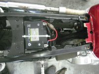
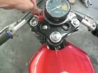
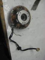
I've been going crazy for a few days over a CB350 I bought. I am 17, foolish, and decided to buy a CB350 that was set up for racing- thus, the wiring consists of a battery (which is to be re-charged after races), a kill switch, and a total loss system (to fire the coils). This is perfect for racing, but I want a commuter bike. All I have for wiring is the alternator, so I'm beginning to tackle the rest of the beast. I only want to run a headlight and a brake light so it's street legal, and, of course, the battery needs to charge. Due to the setup of the bike, I will be roll-starting it. Every time.
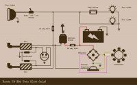
I'm up for building my own harness, but could anyone point me to a good, stripped-down wiring diagram? I read through Sonreir's super-awesome Electricity 101 post, and it sort of makes sense, but I don't fully get why wires run to one place or another. Also, I'm assuming I'll need a regulator/rectifier. Can I buy any old set? Or could I grab an automotive one from Advanced?
 
I'll help you with this one as much as I can, as I recently did this. Kickstart only, headlight, tailight, brake light, as well as installed a relay at the headlight switch.

The attached diagram was a really good start for me, but note the 30a fuse, you only need a 15a.
-What kind of battery do you have?
-I went with a gel battery, stock regulator, and a radioshack rectifier guys have noted on hondatwins.net. search that and you'll find the goods. The stock rectifiers are known to be junk so I just said I'll give the radioshack modern upgrade a try.
-The bike has been running great, battery charging, and no issues. A lot of other modern mods are really pricey, and I'm just not that fully driven to invest in those yet.
-I connected the white and yellow wires (coming from the stator) to allow a more potent charging scheme, since I dont have the stock controls on the bars. I can take some pictures if you'd like.
-I got a headlight switch from dime city that has been clean and simple. $25, cant find em anywhere.

Let me know what questions you got, could help if I could. and hope others can chime in on what ya need.

-Matt
 

Attachments

  • wiringdiagram.jpg
    wiringdiagram.jpg
    71.6 KB · Views: 5,303
If you are using a Lithium battery, upgrading your voltage regulator is going to make it less likely that you end up with an expensive doorstop.
 
Basically, you're going to want the addition of a few things to make the bike more streetable.

Assume you want only coils, head light, tail light, and brake light.

All of these things will need power and so you need a wire running from the battery to each of these items. This is the simplest configuration, but it's still not correct. You'll now notice that your coils, head, tail, and brake lights are now on all of the time (or until your battery is dead).

To control if a device is on or off, you need a switch. So now you install a switch for the coils (kill switch is the switch for the coils, so you already have this one), head, tail, and brake. The head and tail can share the same switch, so when you turn it on, the headlight and tail lights come on together. The brake switch is generally operated by the appropriate foot and hand controls.

So now, instead of wiring directly from the battery to your coils and lights, you wire from the battery to the switches to the coils and lights. In the case of needing two switches for the same light (like the brake light), you'll need two wiring runs. From the battery to each switch and then after each switch those wires can be spliced for a single connection to each light. Now we're getting somewhere.

There is usually one more consideration and that is a master on/off switch. In stock bikes, this is the keyed ignition, but it can be just about any switch with the correct amp rating (15A or better will almost always suffice). So we now include a switch that controls all our switches and those switches control each light.

The wiring run now looks like a single wire (14 AWG) running to a 15A switch. From the switched side of your main switch you have wires running to four more switches (kill switch for coils, one for the head and tail, and two for the brake). 18 AWG wire is sufficient for each of these runs unless you plan to use a high beam, then you'll want 16 AWG for the headlight. From each of those four switches, the wires will run to the device that needs power.

Finally, you need each electrical device to have a return path to the battery's negative terminal. This is often called a ground wire. It it not necessary that each component have wires running back to the battery as the battery should be grounded to the frame. This means each component can have it's negative connection directly to the frame or other exposed metal on the bike. This is the preferred method as it keeps heat in the wiring harness down to a minimum and cleans up the wiring runs significantly. On the down side, it can make trouble shooting a faulty ground a little complex at first because single components may drop in an out if you encounter a grounding issue.
 
In regards to the charging system, I highly recommend an aftermarket regulator/rectifier combination. They're a lot easier to wire up than the individual units as they're contained in a single unit.

In the case of the charging system, the stator will directly connect to the rectifier, whose task it is to convert the AC voltage from your alternator to DC voltage used by the battery and the rest of the bike. The regulator's task is to ensure the voltage generated by the alternator does not exceed a certain level (usually 14.2V for a healthy, modern regulator).

For single units, the wiring runs will be directly from the stator to the rectifier and then from the rectifier to the battery (no fuse, no switch). The depending on the type of regulator, it may sit on the switched side of the circuit (after the main switch), share connections between both sides (as in the case of the Honda twins. Yellow wire is AC, but the black wire is DC), or solely on the unswitched side (almost all combination R/Rs sit in between the battery and stator without making contact to the switched side of the circuit).

Though not mentioned in this post or my previous, it's always a good idea to ensure you have at least one fuse prior to your main switch, but not in between the stator and the battery. 10A will suffice in your circuit, but 15A is usually used for bike with signals, gauges, etc. Generally speaking, the gauge of the wires you're using will dictate the size of the fuse necessary, but fewer and shorter wiring runs will also allow for slightly larger fuses than what would normally be chosen by the factory.
 
If it were my bike, I would also use relays to get the most juice to the headlights...I'd probably use one for the coils, too. This is especially true if the switches on the bike are as old as the bike...

For blinkers and taillights, use LEDs. They're brighter, last forever, and use less juice. There are a few good LED headlights that are excellent upgrades to CB lights and H4s, but they cost a few hundred bucks, and you should probably get the rest of the bike sorted before bothering with them.
 
Thanks to everyone! I really appreciate the help.
To onelifematt, I'm happy to know it's possible and I'm not the only one (being new to this is a bit daunting). Also, great diagram. But I have a small 12v xtreme racing battery (I say racing because it's small, not big enough for an electric start or anything). I looked up the Radio Shack rectifier, and that looks like a good deal, but I'm really hooked on the idea of the reg/rec combo, which bring me to ask...
If I bought a piece like this
http://www.ebay.com/itm/REGULATOR-RECTIFIER-REPLACEMENT-KOHLER-JOHN-DEERE-AM34738-AM106357-R8969/321040353747?_trksid=p2047675.m1850&_trkparms=aid%3D222002%26algo%3DSIC.FIT%26ao%3D1%26asc%3D11%26meid%3D8186916210288660165%26pid%3D100011%26prg%3D1005%26rk%3D2%26sd%3D200647323471%26
How do I wire that up? I see that it has three prongs. I'm sure it would come with instructions, but there are three wires coming off the alternator, producing AC current, so where do those attach? And from there, does that simply run to the positive side of the battery and the connection it would share with the ignition switch? (Which then would run to the various accessories).
I'll include some pictures and see if that helps. By the way, my thumb is on the ignition switch. The alternator, I know how to install, but my big question is- what do I do with the three wires and the reg/rec combo?

Thanks!
-Nick
 

Attachments

  • IMG_8776.JPG
    IMG_8776.JPG
    954.3 KB · Views: 469
  • IMG_8777.JPG
    IMG_8777.JPG
    866.4 KB · Views: 396
  • IMG_8778.JPG
    IMG_8778.JPG
    420.2 KB · Views: 383
  • IMG_8780.JPG
    IMG_8780.JPG
    885.6 KB · Views: 434
Instructions:

http://www.hondatwins.net/forum/viewtopic.php?t=14530

Watch out for slightly cheaper Chinese clones:

http://www.hondatwins.net/forum/viewtopic.php?f=16&t=22444
 
Before I proceed, does this look like it'll work? No major errors?
Also, thanks Rich Ard for the Honda Twin instructions- this diagram is a combination between that and Matt's CB350 kickstart diagram.
 

Attachments

  • CBwiring.JPG
    CBwiring.JPG
    28.7 KB · Views: 460
You will want the relay for the headlights to be controlled by the light switch. So, the handlebar switch turns the relay on/off, and the real current is brought to the relay directly from the battery (so two hot wires to the relay, can be part of the same fuse).

It's not necessary, but you will get better lighting.
 
Back
Top Bottom