CB350 points adjustment (newbie question)

druckson

New Member
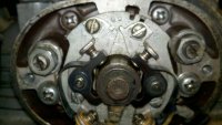
So I've been having some issues adjusting the points on my 72 CB350. My manual (I'm using the Honda manual) is pretty light on the details, so here's what I did:

1. Loosened the breaker locking screws and set the clearance to 0.35mm, re-checked after tightening.
2. Hooked a test light up to a cooling fin, and held the tip to the spring on the left point.
3. Turned the crankshaft at the alternator counter-clockwise until the light turned on.
4. Did 2 and 3 for the right point.

So for the left point, the light turned on well after the LT mark on the alternator rotor. I turned the points plate clockwise until it wouldn't turn anymore (this points plate has a slot that limits its turning angle), but it ended up between the LF and the LT marks. At that point I tested the right point and it was well after the LT mark. So it seems like for some reason the points cam is off by so much that I can't adjust the points to compensate for it. I'm at a loss as to where I should go at this point, any advice?

Thanks,
Druckson
 
This is the method I use (taken from HondaTwins.net)

  • When you set the gap on the left points, you should do it when the points are at their widest opening (the "follower" is on the highest "bump" on the breaker cam of the advance unit).....
  • Lock the left point screws down to keep it at the .014 gap on the plate....
  • Then, with crankshaft now rotated and held on the LF index during the left compression stroke, rotate the entire plate to get the left points to just open (light the light) and lock down the plate ......
  • The plate MUST remain where it now is, no further adjustments are made to the plate....
  • Rotate engine to the F index of the right compression stroke..
  • Set right points to just break .....
  • Lock the right points down.......
  • Now you check the right points gap by rotating the engine until its follower is on the biggest bump.....
  • If it is anywhere within the spec range, you are done....
  • Don't adjust the right gap (or anything else) further.....
  • Gaps do NOT have to be any certain amount or even... just within the spec range.....
 
Thanks for the response Herr, I used your directions, but I ran into the same issue. I'm posting pictures of the points and the alternator where they are when the light goes on. As you can see, it's a little bit late, and I'm not able to advance the timing any further. Any ideas what could cause this?
 

Attachments

  • 2012-10-13_16-54-01_185.jpg
    2012-10-13_16-54-01_185.jpg
    1.5 MB · Views: 2,932
  • 2012-10-13_16-56-04_413.jpg
    2012-10-13_16-56-04_413.jpg
    1.7 MB · Views: 1,251
I use the same steps HerrDeacon indicated.

It may help to visualize what's happening in the coils. You may already know this, but if you don't, and for anyone else that may benefit from it, here goes:
Consider your left point breaker. When the breaker is closed there is a path from the battery, through the primary winding in your ignition coil and grounds through the other side of the breaker. this current flow effectively charges the secondary winding in the coil creating a decent-sized magnetic field. When the breaker opens (because the larger bump on the points cam has pushed against it), there is no longer a path to ground and thus, current stops flowing through the primary winding. Without this current flowing, nothing is supporting the magnetic field that has been built up and it collapses very quickly (in the form of a big-a$$ spark) out the end of the spark plug wire and jumps the gap.

Now your test light works by "detecting" when the points open.

So basically, that's how the ignition works on these types of systems. There's a couple of other things going on with condensers. but for the most part, it's really that simple.

Had this worked before you opened it up (although maybe poorly?). The reason i ask is it's fairly easy to install the points cam 180 deg off if you're not paying attention and just finished replacing the advancer. Could it be possible that it was installed incorrectly?

Also, sometimes where the wire attaches to the spring clip at the bottom of the baseplate can ground against the plate or the cover, screwing with your results.

Other questions to ask:
are you sure you're on the compression stroke when the points just begin to open?
have you verify that they're wired correctly?

Hope some of this helps someone.
 
Also be aware that the points only open every other rotation of the crankshaft. I see that they're closed when you're at LT, so try turning the crank another 360° (back to LT) and see if they're open.

If not, you have some adjusting to do. If they open pretty far off from LT, then it's possible your advancer is 180° out.
 
Thanks for the responses Jrasm and Sonreir. Jrasm - OK, that makes sense. It was a bit weird to me that the opening of the points corresponded to the spark, but that's reasonable.

So, I was able to finally fix the problem, and as I suspected it was a dumb newbie mistake. It turns out I was using the wrong feeler gauge (something like 0.03mm rather than .3mm), so the points were opening way later than they should have been. After correcting that I was able to get them set in a matter of minutes...

Thanks again for the help,
Druckson
 
Even .3mm is a bit on the thin side. I aim for .015" when I do mine for the left points. Right side should be between .013" and .018", if I remember correctly. The left side timing gets set by rotating the points plate and the right side timing is set by changing the gap.

If you get too thin on the right side, you can try taking a points file to it. Too thick and you can file the left and change the rotation a bit. Might just be easier to buy new points if you get to that stage though, they're pretty easy to come by.
 
Remember, points are set to open at LF and F. If you have the cash just get a Pamco ignition. I love mine on my 350. They are very affordable and make a huge difference.
 
Hey guys, sorry for the delayed response, it's been a while since I've been able to work on the bike.

djelliot - Looks like a cool system. A bit more than I want to spend at this stage, but I'll keep it in mind for the future.

Sonreir - Yeah, my manual says 0.3mm-0.4mm. I ended up setting both to 0.38mm, rotating the plate to time the left side, then adjusting the right side gap to time the right side. The static timing is looking pretty good, but I have no idea about the advance. On another note, it looks like I'm going to have to rebuild the engine, so it'll be a while till I need to worry about timing again.
 
pamcopete said:
I think I'm going to frame this!.... ;D

I'm struggling with points on my CB360. I can't WAIT until Pete has EI for the 360's!! :p
I am so jealous of the other CB's who have it already. :(
 
Wangofree said:
I'm struggling with points on my CB360. I can't WAIT until Pete has EI for the 360's!! :p
I am so jealous of the other CB's who have it already. :(
Actually, I am not a fan of EI but after 5 year going with point I see it is high cost (point is expensive), hard for maintenance and very easy to be burned (possibly the new production of point is not good). So I decide to move to EI. I paid USD 400 for EI from Bore Tech and use it with 1 year then one day, it simply died. So I make my own electronic ignition. It is simple if you could do some machining, then HEI ignition module is great EI module for stock coil (you need 2 of these 4 pin type), hall effect sensor could work as point function and it is located 90 degree on the "point plate". the sensor as 55100 hall sensor will work.
I make and sell several IE for CB350 and it runs great from 1000 rpm to anywhere around 9000rpm. Fast respond and easy to replace or fix , no black box as sensor and IC is very popular.
The only thing that hard is making the "magnet" disk which act as a sensor trigger . I machined it with both stainless steel and aluminum disk to avoid wear/ broken of the tips (if made all of aluminum) at high rpm while minimum the centrifugal weight.
For me ignition system now not black box anymore. You could do it your self and have fun with it.
Viet
 
Viet said:
Actually, I am not a fan of EI but after 5 year going with point I see it is high cost (point is expensive), hard for maintenance and very easy to be burned (possibly the new production of point is not good). So I decide to move to EI. I paid USD 400 for EI from Bore Tech and use it with 1 year then one day, it simply died. So I make my own electronic ignition. It is simple if you could do some machining, then HEI ignition module is great EI module for stock coil (you need 2 of these 4 pin type), hall effect sensor could work as point function and it is located 90 degree on the "point plate". the sensor as 55100 hall sensor will work.
I make and sell several IE for CB350 and it runs great from 1000 rpm to anywhere around 9000rpm. Fast respond and easy to replace or fix , no black box as sensor and IC is very popular.
The only thing that hard is making the "magnet" disk which act as a sensor trigger . I machined it with both stainless steel and aluminum disk to avoid wear/ broken of the tips (if made all of aluminum) at high rpm while minimum the centrifugal weight.
For me ignition system now not black box anymore. You could do it your self and have fun with it.
Viet

PICTURES PLEASE! AND SOME DETAILED INFO!!
 
Wangofree said:
I'm patiently waiting for Pamco Pete's "new" EI system, but I too would like to see pix & details Viet.
Hi all,

These are pictures:

AcaciaEI-CB350_zps11c91a09.jpg

IgnitionBox-SandCast-2HEI4pininside_zpsd25935f6.jpg

TriggerRotor_zps79595009.jpg

On the CB450K
AcaciaEI-CB450_zps11ee2cdb.jpg

On the CB350K1 cafe racer (I attached it next to the battery box)
AcaciaEI-CB350K_zps0086dba2.jpg


Specification:
Sensor: I used 55100 hall effect sensor
Ignition Module: HEI 4 pin - Ford/ Chrysler.... each for 1 ignition phase. It means for CB450 and CB350K, XS650, you need 2, for CL175 you need 1
Trigger rotor: 2 disk of aluminum locking together with the "stainless steel leg"
Wiring: just google the "CB750 HEI ignition", I do the same.
Ignition Box: Cast Finned Aluminum with open back so you could open and replace any not in order.
I have not see any bad point of this system. Real good set up compare with those "black box" ignition module.
For safety: you just need some pre-wired 5mm led (LED act as diode in the CB750 HEI module)
My Price: sorry but higher than Pete Pamco. It is USD 120 shipped to US. I have sent 2 set to 2 DTT member for honest testing (shipping cost and finned box cost a lot)
Thanks
Viet
 
I checked Digikey for the sensors: 14.45 for 2 plus 2.80 Shipping
Autozone: GM HEI 4 Pin module: 42.99 x 2 = 86.00

About $104 for the main parts, not even complete. So $120 is not bad... Same price as Pamco Petes.

But Pamco Pete offers technical support and warranty.

But a nice effort there....I do like it. If I had access to parts a lot cheaper, it would be a viable alternative.
 
mydlyfkryzis said:
I checked Digikey for the sensors: 14.45 for 2 plus 2.80 Shipping
Autozone: GM HEI 4 Pin module: 42.99 x 2 = 86.00

About $104 for the main parts, not even complete. So $120 is not bad... Same price as Pamco Petes.

But Pamco Pete offers technical support and warranty.

But a nice effort there....I do like it. If I had access to parts a lot cheaper, it would be a viable alternative.
Yeah,
Thank you and you are right. I make it happened as I am bulk buyer so price is much lower than retail. Second, I made my mechanic parts myself so cost much lower (though if I made the rotor using aluminum, it is much cheaper and easier). Guarantee is ok. I just make a EI that its parts are replaceable and real good ( so price could not be lower)
Thank
 
Viet said:
Yeah,
Thank you and you are right. I make it happened as I am bulk buyer so price is much lower than retail. Second, I made my mechanic parts myself so cost much lower (though if I made the rotor using aluminum, it is much cheaper and easier). Guarantee is ok. I just make a EI that its parts are replaceable and real good ( so price could not be lower)
Thank

Viet - Do you make these for the CB360? Or just for the 350's & 4 cylinder motors?

I think your Bore-Tech experience would scare off a few buyers of that system. :eek:

Thanks
 
Wangofree said:
Viet - Do you make these for the CB360? Or just for the 350's & 4 cylinder motors?

I think your Bore-Tech experience would scare off a few buyers of that system. :eek:

Thanks
Hi guy,

I don't think Bore Tech product is not good. It runs great but since its electricity complication and blocked (I have tried to open to fixe it once on my set) so it makes user become a dump on understand of the system. Once it failed, you have to buy a new one.

I develop a system based on "mechanic experience" not electrician. It means, the system must be understandable, no black box, easy to replace/fix ( as in your Ford), durable and race able.
I test the system on continuous 1000 miles ride (Saigon - Hanoi) in 4 days and no even a small issue. My Cb350 got 2 Mikuni VM30 standard jetting, pistons from CB360T and the electronic ignition from mine. It runs like champ that I never get full throttle of its though it get me 9000rpm already.
I am buying CB360 advance mechanism and point plate. If it is the same with CB350K then it is sure that CB350K and CB360 could use the same electronic ignition.
I could make one set for you if you send me your point plate and advance mechanism from your CB360, if it is the same, I will send you a set of CB350 (price will be only 75 shipped) if it is not, I will make a new set based on your advance system and the price is 90 shipped. Your advance and point plate will be sent back to you.
Best regards
Viet
 
Back
Top Bottom