dartyD
Active Member
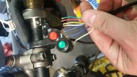
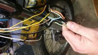
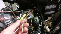
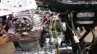
So I have a 1971 cl350 and I'm trying to wire in this button control. Has anyone ever used this before on a bike similar to mine? The problem I'm having is figuring out what is absolutely necessary for the bike to run.
dartyD said:So I have a 1971 cl350 and I'm trying to wire in this button control. Has anyone ever used this before on a bike similar to mine? The problem I'm having is figuring out what is absolutely necessary for the bike to run.