Diagram critique

rachsrib

New Member
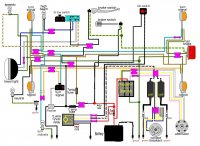
Getting ready to jump into rewiring my cb360, Found another member's simple wiring diagram that I liked and made some tweaks to eliminate the starter and starter junction.

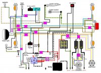
I have a Kohler R/R unit. Eventually I will need to diagram the speedo/indicator lights I am using as well as the aftermarket switch, but I wanted to make sure I deleted the starting circuit correctly first.
Thanks

2572-210115115855.jpeg
 

Attachments

  • cb360 with relay edits.jpg
    cb360 with relay edits.jpg
    181.9 KB · Views: 253
Great! Time to start tearing into it then, would you change anything knowing that I will be using LED turn signals and Indicator lights, other than wiring in the diodes on the correct signal wires?
Thanks
 
I'd skip the relay for the coils unless you plan on moving to the 3Ω variety. I'd use a Sparck Moto R/R instead of the Kohler clone as well, and I'm not just saying that for the extra business. The Kohler units aren't that much cheaper than ours, and ours outperform them in almost every single metric.

Also, I'm assuming you're wanting the running lights and parking lights?
 
Yeah I was hoping to keep the ignition switch pretty stock with the parking and running lights. The switch I am using will just be a hi/low switch so all time running lights.

With LED do the coils get more power? I thought a relay was to provide the different systems (coil and headlight) with a stronger signal.
Looks easy enough to delete the relay out of the diagram if the relay is serving no purpose.

Thanks
 
rachsrib said:
I thought a relay was to provide the different systems (coil and headlight) with a stronger signal.
Looks easy enough to delete the relay out of the diagram if the relay is serving no purpose.

It is, but the difference doesn't matter that much unless you're using components that draw high power such as 55W+ bulbs and 3Ω coils. 35W bulbs and 5Ω coils are just fine with direct runs.
 
Ok, looks like I am more or less back to your simple wiring diagram posted here: http://www.dotheton.com/forum/index.php?topic=52092.0

One other question, the stock kill switch is an actual turnable switch, the one I am going to use is a momentary switch. In my head it would work the same, since when it is pushed down it will break the power circuit to the coils.

Also using the diodes on the turn indicator light and purchasing a newer style flasher relay from you, should be all I need to do if I am planning on wiring directly to other LED indicator lights and a LED tail light correct?

Thanks for the help, once this is done my bike will hopefully start again!
 
So that five pin relay will be necessary if you want a momentary kill switch. Momentary switches are almost always NO (normally open) rather than NC (normally closed). This means when you push the button, you get a connection, rather than breaking a connection. They work great for bikes with CDI systems (like most dirt bikes and some models from the early 80s).

Going back to the idea of the five pin relay, you can have power to pins 87a and 85, then output to the coils on pin 30, and output to the push button on pin 86. Pin 87 unused. With this setup, you have power running to the coils all of the time, except when you complete the circuit for the energizer on the coil, then it breaks the connection between the power and the coils and kills the engine.
 
Thanks, knowing that saves alot of head scratching when the bike wouldn't turn over. I am redoing the diagram to reflect some of the things I just learned.
 
Ok here is the update. I have a question about grounding the relay, all the diagrams I see shows the 85 pin being the ground. Will I need to ground the relay still off of the 85 pin?
 

Attachments

  • cb360 with relay edits.jpg
    cb360 with relay edits.jpg
    184.8 KB · Views: 247
After reading a bit more about relays and thinking things over, I think the kill switch (momentary button) would actually be the ground.

Is that right?
 
I am a bit stumped now. I wired up most of the diagram, Reg/rec, relay, kill switch, points/coils and alt. I didn't wire the "brown or blue and orange" circuit above because I don't have the turn signals or lights yet but I dont think it should matter.

I didn't wire the ignition switch. I had just planned on testing the system by connecting black and red together where the key should be in the diagram.

I am using a testing light hooked up to the points to verify power to the bike.

The problem is that the bike always seems on. The relay works, when the button is pushed down the system grounds out and dies but other than that, as soon as I hook up the battery, my testing light on the points light up.

Am I thinking about this right? shouldn't the bike have no power until Red and Black are hooked together?
Thanks
 
That's correct. No power until black and red are connected. It sounds like black and red are connecting somewhere else in the circuit (other than your ignition switch).
 
That's is what I thought. I am going to look at it on my lunch and remove any wires that might be connecting to black but at first glance I didn't see any.

With only green black and red running you would think it would be simple, haha
 
Back
Top Bottom