DIY Rearsets

paultsmith

Active Member
Here are the rearsets that I have been working on for a while.
You may have seen my cardboard mockup post here. http://dotheton.com/index.php?topic=7056.msg60372#msg60372

I finally got around to cutting out the rearsets and mounting them. The only change I needed to make was that I got rid of the bronze bushing and replaced it with a 3/8" ID bearing. The bushing wasn't allowing the lever to travel smoothly. The bearing is super smooth, used the same bearing from Fastenal as mentioned on a previous post.

Everything shown below in the photos was done with a jig saw, some files and sand paper drums mounted in my drill press. I bent the levers to solve my clearance issues and then went back to hack out the lightening holes. I didn't want to try to bend the lever with the holes in it, as it would have bent around the holes and in the wrong place.

The toe peg is just a sleeved bolt with the sleeve removed. I placed a piece of rubber fuel line over the sleeve. Very cheap. The pegs are BMX pegs with a 3/8 bolt.

I needed a bracket to mount these to the frame and since I wasn't planning on chopping anything off of the frame I planned on using the existing bolt holes for the passenger pegs and the old exhaust hanger mount. The bracket is just another piece of 1/4" aluminum. To get the "bling" factor (engine turning), I mounted a 3/8" wooden dowel in my drill press and dipped the end in valve grinding/lapping compound. I put light pressure on the aluminum and then continued moving the piece in 3/8" increments.

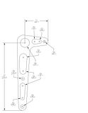
I just mounted the brake lever and bracket this evening, works great. Will take a photo and post it of the shifter and brake on the bike soon, but for now here are some images of the rearsets for the brakes before I mounted them.

Total price for the 2 levers and 2 brackets $75
Aluminum 4"x20" $25
Bearings $5
BMX Pegs $10
Aluminum Rod for Pushrods $5
Throttle Ball links $25
Misc (Bolts & fuel line) $5


This was my first time working with aluminum and was putting this off cause I thought it would end in a disaster. I was surprised how smooth everything went and will be fabricating some more for my next build.

r1.jpg

r2.jpg

r3.jpg

r4.jpg


I'm a big fan of machinist jeweling, good choice.
I'm presently working on my own set as well, good job!
 
Hi Paul,

This thread is a real help! But I'm kind of confused about something.

That bearing is 3/8 inch diameter. And the footpeg bolt is also 3/8". Isn't there any sleeve or bush over the bolt, or the bearing is directly on the bolt and rotates over it?!?!
r1.jpg


When you tighten the footpeg, lever and bracket together - how does the lever move?! Won't it be jammed with the absence of a bush or sleeve?!
r3.jpg
 
The dimensions of the bearing are 3/8" inner diameter, 7/8" outer diameter and it is .281" wide.
The bearing is placed directly on the 3/8" bolt that holds the footpeg.


If you look at the bearing you will notice that there is an outer ring (race 7/8"diameter) and and inner ring (race 3/8" diameter). These races are .281" wide however the space in between these is about .2" wide. This reduction in width is what enables you to hold the bearing in place with 2 washers.

If you look at the first photo you will see that I have 2 bronze washers. One is placed on each side of the lever. They are about 3/8" inner diameter and 0.65" outer diameter. You just need a washer that is about as large as the inner race of the bearing and just smaller than the outer race. In this case somewhere around .4" to .7"

When I tighten the footpeg the washers squeeze up against the inner races of the bearing and cause the inner race not to move. The outer race and balls of the bearing are then free to rotate around the inner race. The bearing in fact does not really spin on the bolt, the inner race is held really tight (its sandwiched between both washers and jammed between the footpeg and the bracket). If it helps you can just pick up a bearing and see how it spins, just hold the center ring and you will be able to spin the outer ring, that is basically how this lever is operating.


The aluminum for the lever is .25" wide so the bearing is just slightly larger than the aluminum plate. I used a stepped bit to drill a hole slightly less than 7/8" and then used some emery cloth to widen the hole. I placed the bearing in the freezer overnight to hopefully shrink it a bit and heated my lever (not sure if this helped). Then I tapped the bearing in place and it gave a nice tight fit.

I can tell you that the movement is super smooth, like spinning a wheel on a skateboard.
 
Heck you are maddd! :) This is good stuff! Thanks for answering the question in a very simple yet descriptive manner.

I'm working on a friends Enfield now. The brake rearsets will be having this setup, since the brakes (and linkage) are on the left side. This post will help me a lot.

I placed the bearing in the freezer overnight to hopefully shrink it a bit and heated my lever (not sure if this helped). Then I tapped the bearing in place and it gave a nice tight fit.

You even answered my next question in advance!
 
Thanks,

For the rear brake I wanted to keep everything pretty much the same, so if desired I could go back to the stock setup. I also didn't want to touch the pushrods that were there or have to worry about the brake light switches.

What I did was get a spare brake pedal. Then I cut off the pedal and arm, leaving only the spline. I then welded a small piece of steel onto this female spline piece and placed a ball linkage joint on this. I then connected a threaded rod between the ball joint on this spline piece and the ball joint on my new rearset lever. I'll try to post a photo tonight, I have just been using a scrap piece of rod to get the length right. I need to cut and polish the final aluminum push rod, but it will give you the idea.
 
Step one complete. Progress:

Bolt: Its quite long, so I can cut off how much ever I need. I think its a 10mm bolt.
Ball bearing: Got the perfect size. Think its 3/8" itself.
Lever: I've given the drawing to a guy who will cut it out in metal. They do not use aluminium. Will be cutting off holes to make it lighter.
Washers: Got two very small washers that only hold the inner ring.

Fitted the bolt, washer, bearing and nut tightly and tried spinning the bearing. Works like a charm!

He'll probably get the levers done by tomorrow. And if it is ready, I'll get to see them on saturday. Till then here are two attached pics.
 
TDC said:
What technique did you use for the jeweling?

TDC,

Jeweling:
I mounted a 3/8" wooden dowel in my drill press and dipped the end in valve grinding/lapping compound. I put light pressure on the aluminum and then continued moving the piece in 3/8" increments.

This "grinds" in a 3/8" circle, then I keep moving in increments of 3/8" down a column. When I get to the end, I just start over, however I offset the next circle.

I printed a pattern of points and taped this to the base of my drill press. I then held a straight edge against one side, and marked a refernce point on my piece, I just moved this reference point over all of the marks I had, until I had grinded in a bunch of circles.

Here is a look at the pattern on my drill press.

DSC_4198.jpg
 
Brownell's sells a gunsmith's jeweling kit that's the tits if you plan on doing more than the occasional piece.
 
Mounted everything up:
Left the shifter linkage pretty long, I will shorten it and fine tune, after I check it out riding. For the shifter side, I also needed some extra strength on the long linkage rod. The 1/4" aluminum would bend if I shifted hard. Solution: Placed the some 1/4" ID stainless steel tubing over the 1/4" OD aluminum rod"

Just need to clean and polish everything. I am also looking for some better nuts and bolts, Not digging the head and haven;t been able to find any acorn wahsers for 1/4" fine threads.

Everything is working fine, shifting and braking is smooth.

The only thing is that I had to have everything up fairly high, as I don't want the peg to hit the exhaust. May not be so bad once, I get the seat done as I the riding position will be up higher.


DSC_4183.jpg


DSC_4184.jpg


DSC_4190.jpg


DSC_4191.jpg
 
From what I've read and seen, the ideal setup is to have the shifter or brake attachment parallel to the footpeg upright part (shit, do any of these parts have real names?)

You get what I mean. Is there a reason your brake side is so short? Doesn't look like it would work very well.
 
Swagger said:
looking good! Does the kicker clear?

Kickstarter will clear, however I need to trim off about .3" from the rubber-piece/bolt brake lever. This is just a quick job, much easier to cut this rubber and bolt then bending the kicker. There is still lots of room for me to press the brake with my toes.

There is no interference from the BMX peg and kicker.
 
Back
Top Bottom