Down under, an idiot and a 400F

Cool stuff.
Check the compressed length of tensioner springs, it may already be close to compressed position.
The plunger does slide further with lock bolt removed but the flat machined on limits travel with bolt in place?
How did you get the 'horseshoe' to stay in place? usually it will drop due to gravity when it's upside down
Tapping stainless is always a problem, it work hardens if you back out tap like your supposed to. then grabs tap tight
I find using a tap with top of threads removed helps even if you have the full set of starting, taper and plug taps (use a sharpening stone- carefully)

Oh, be careful not to over-tighten chain with manual adjuster, only do it when engine is fully hot as it will get 'longer' so chain gets tighter
 
This is the plunger fully compressed with springs on:


Looks pretty much fully compressed so I'm assuming this is ok?

Also the horseshoe pic was rotated 90 degrees, hence why it was staying put. You can see my bench in the background.
 
So order went in with Cone Engineering today. Once again impeccable service from Rich. Cannot recommend them enough.

Certainly not the cheapest option, but with the passing on of the Yoshimuras, these weren't a huge amount more and I'm hoping they look as tough as I hope they do.

Once they arrive I need to get my secondary templates sorted so I can get them custom bent, before the whole lot goes back to Darren at DnA Customs for final welding and the exhaust hanger solution made up.

Currently thinking on the exhaust hangers is to weld a subtle bracket to the upright (rear part) of the subframe support and have Darren make up some hangers on his CNC mill. This is the general plan:


I am however concerned the modern hanger may not be in keeping with the design of the bike (classic, retro, modern), so I'm toying with the idea of using round rod painted black to match the frame tubes a little. Eg:


neevo said:

not to threadjack man, but im about to pick up a south bend 9" here soon, and im digging your setup. Could you give me any more info on it? treadmill motor?
 
hurco550 said:
not to threadjack man, but im about to pick up a south bend 9" here soon, and im digging your setup. Could you give me any more info on it? treadmill motor?

Sure. No problem.

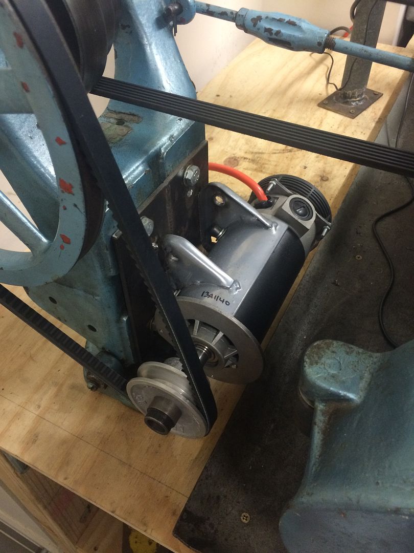
1. I found an Avanti treadmill going cheap on eBay. 99c auction as the motor was making horrible noises. Turns out 2 new bearings and a new set of brushes and it worked perfectly, was also a 2.5HP peak HP motor so plenty more than you would need for a 9" lathe (fortunately the flat belt slips before things get too out of control). I took the motor mount and welded it to a plate for attaching to the lathe motor mount. Plate had elongated holes for adjustment:


Next I bought a pulley from my local bearing shop and opened up the ID to accept the bushing on the end of the motor. The motor was designed to run the opposite way so I had to loctite the bush to the motor as it was on a reverse thread:


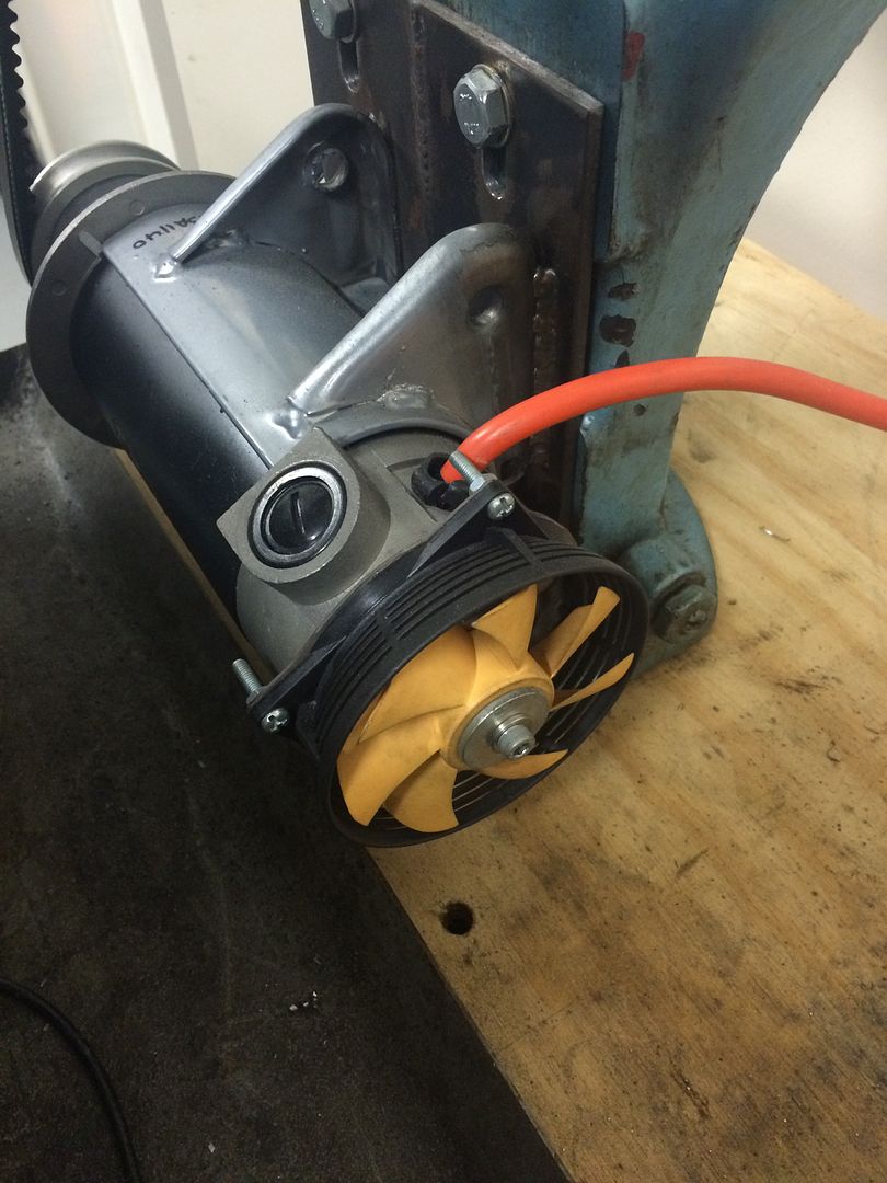
Originally there was a fan on the end of the motor, but because I had reversed the motor it would pull air through it vs pushing. So I bought a fan, fan housing off eBay and made a bracket to connect it to:


The motor was terminated on a high end 10A audio connector which gave me a quick release. Did the same thing with a cheap magnet RPM sensor. I did this for the control box so it was easy to separate all the items vs having it all connected. The things on the left and right are just foam covered holes for ventilation:


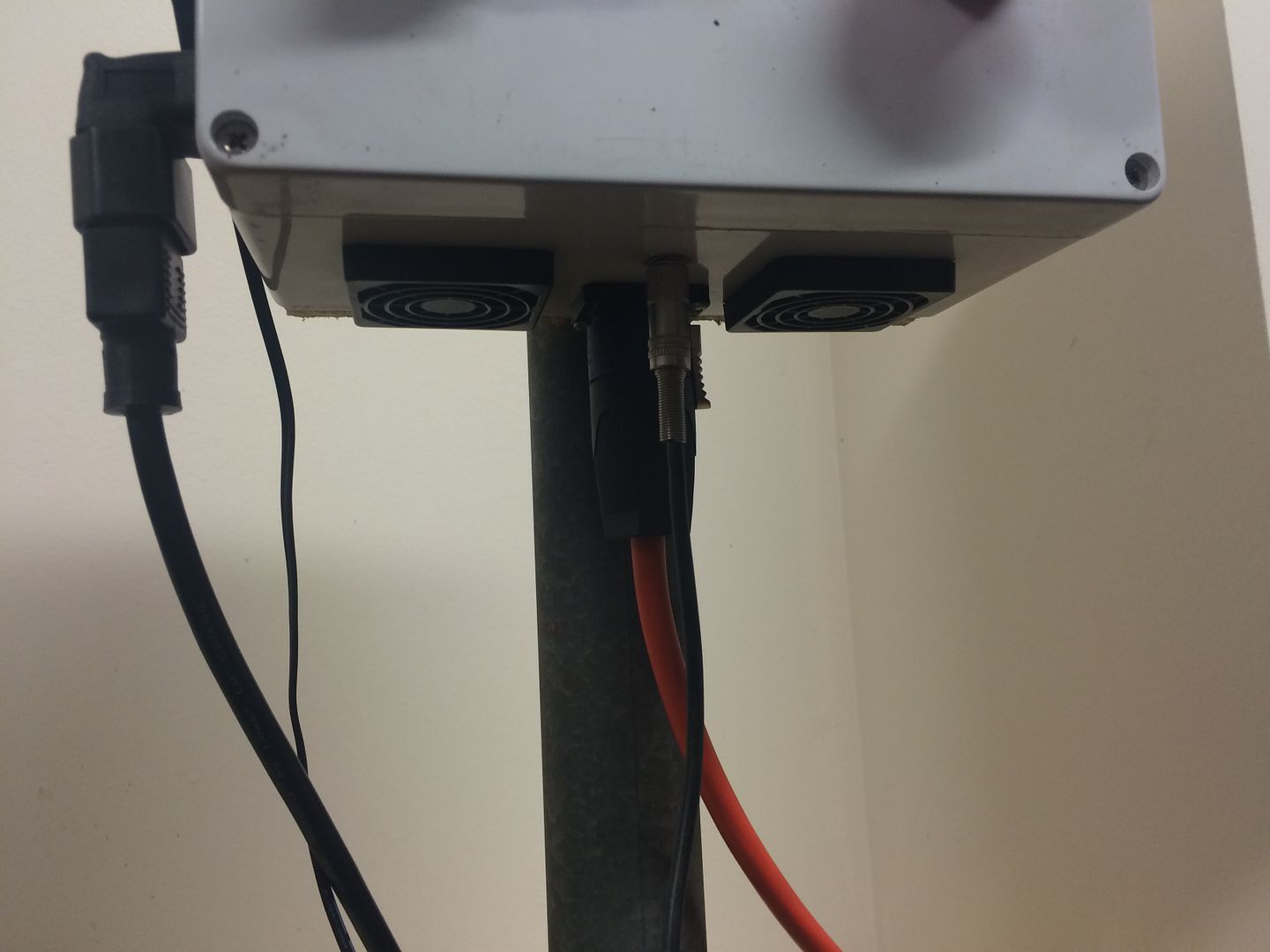
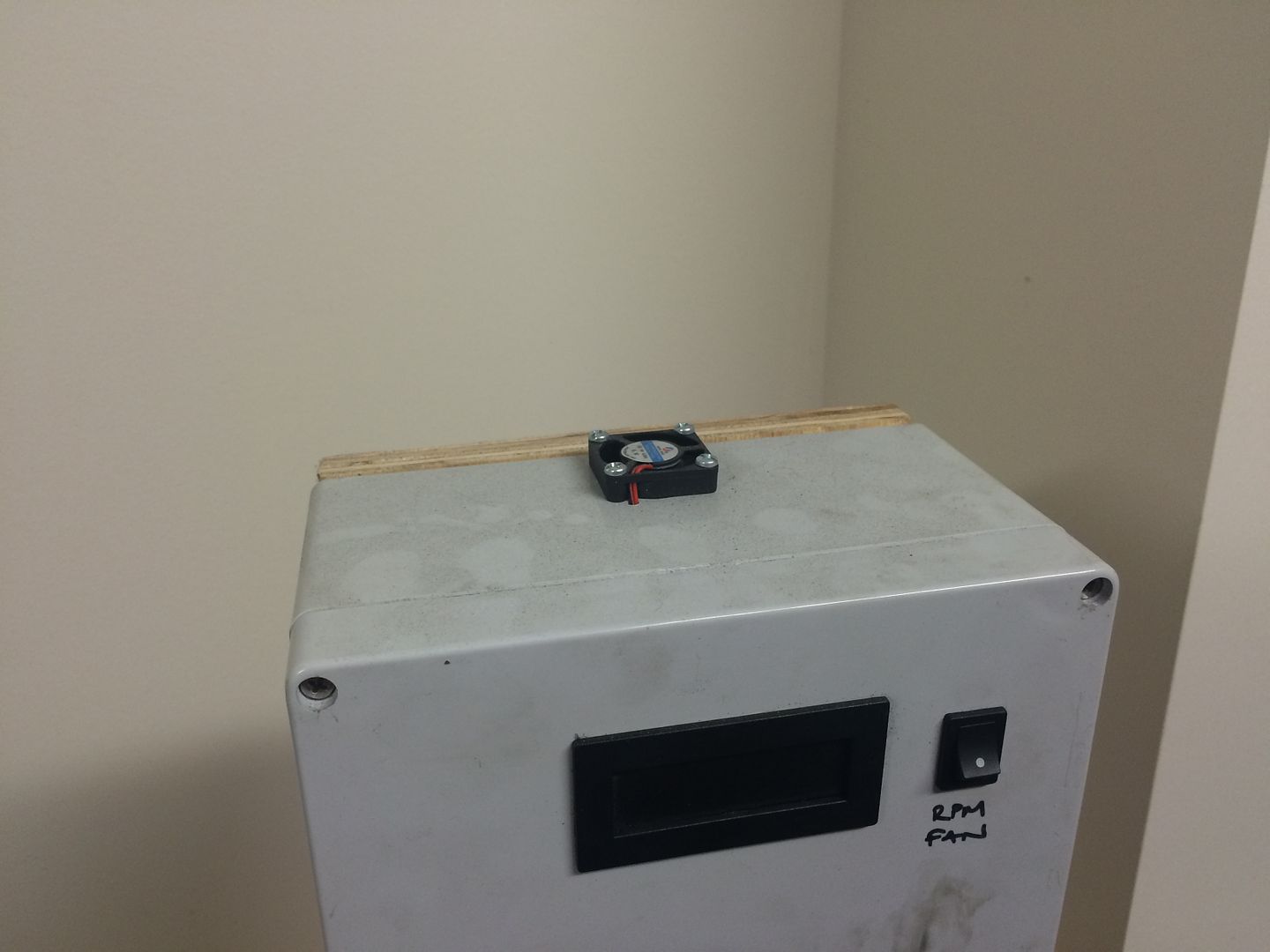
I was worried about cooking the DC motor controller in the control box, so the foam covered holes allowed air to enter and fresh air was pulled through via this fan on the top. The fan is run off the 12V RPM sensor wiring so it all comes on together to keep things simple:


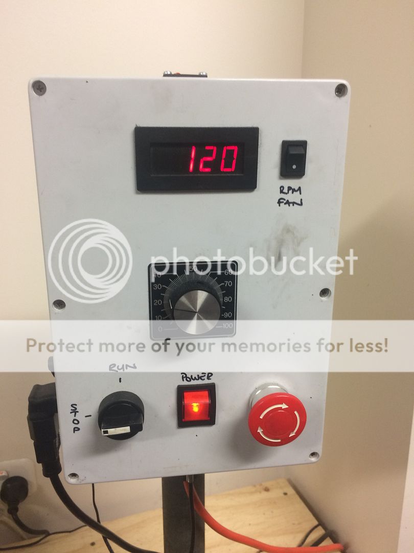
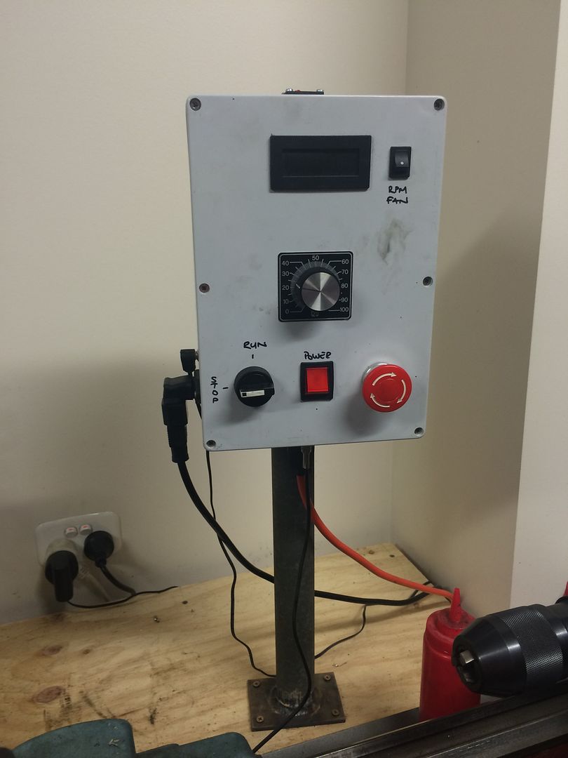
The control box basically has 240V power and 12V power feeds on the left hand side, on connectors so easily removed. Motor and RPM sensor connectors on the bottom. The box contains a KB Electronics DC motor controller with an additional heat sink with fins in the same direction as the air flow from the fan on top. I have an emergency stop button in series with an LED switch for main power, a black rotating switch to activate the motor, potentiometer for speed control and the RPM dashboard with a switch next to it to turn it (and the fan) on/off:


The RPM sensor was attached by bending up a small piece of Alu:


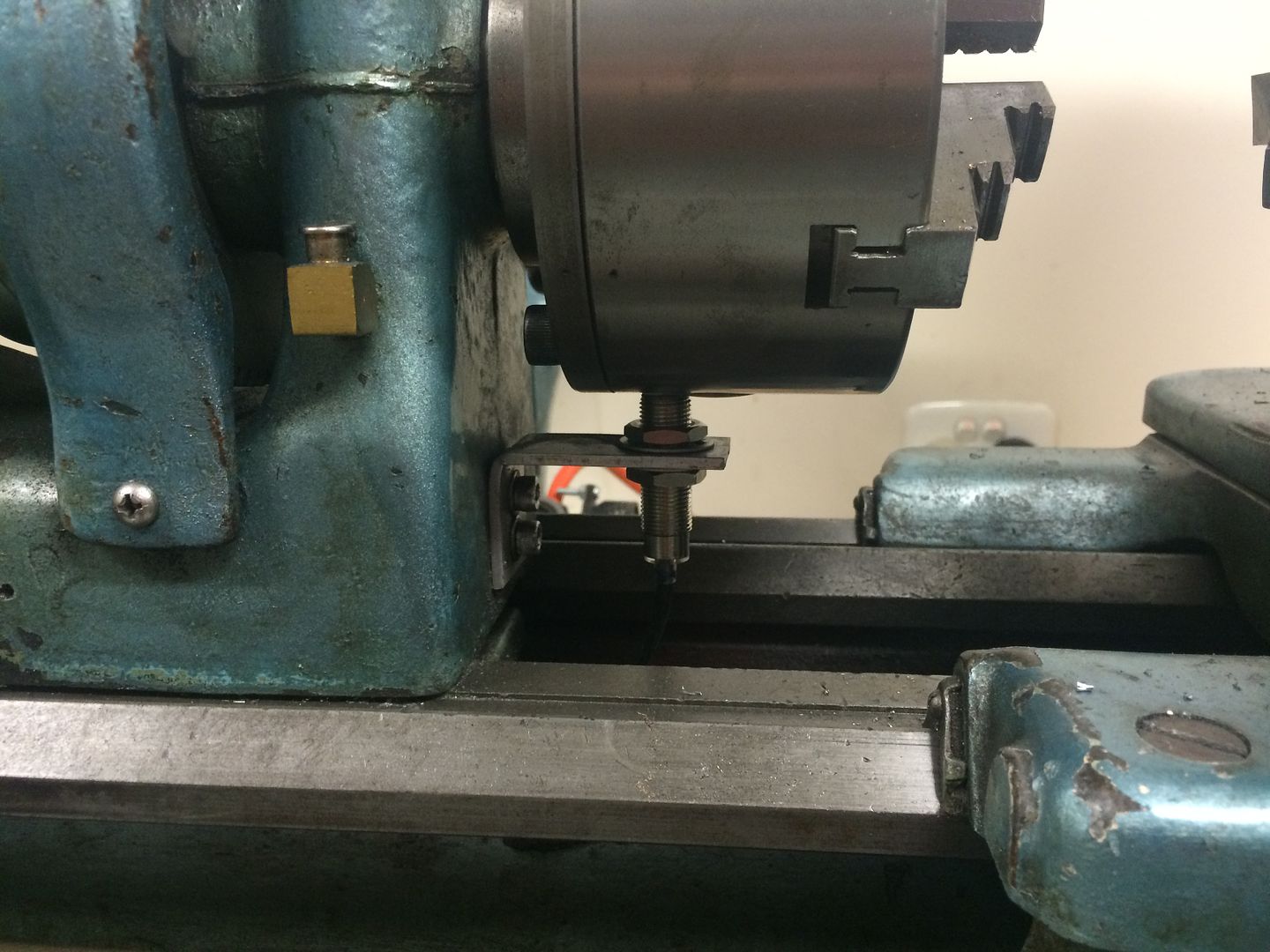
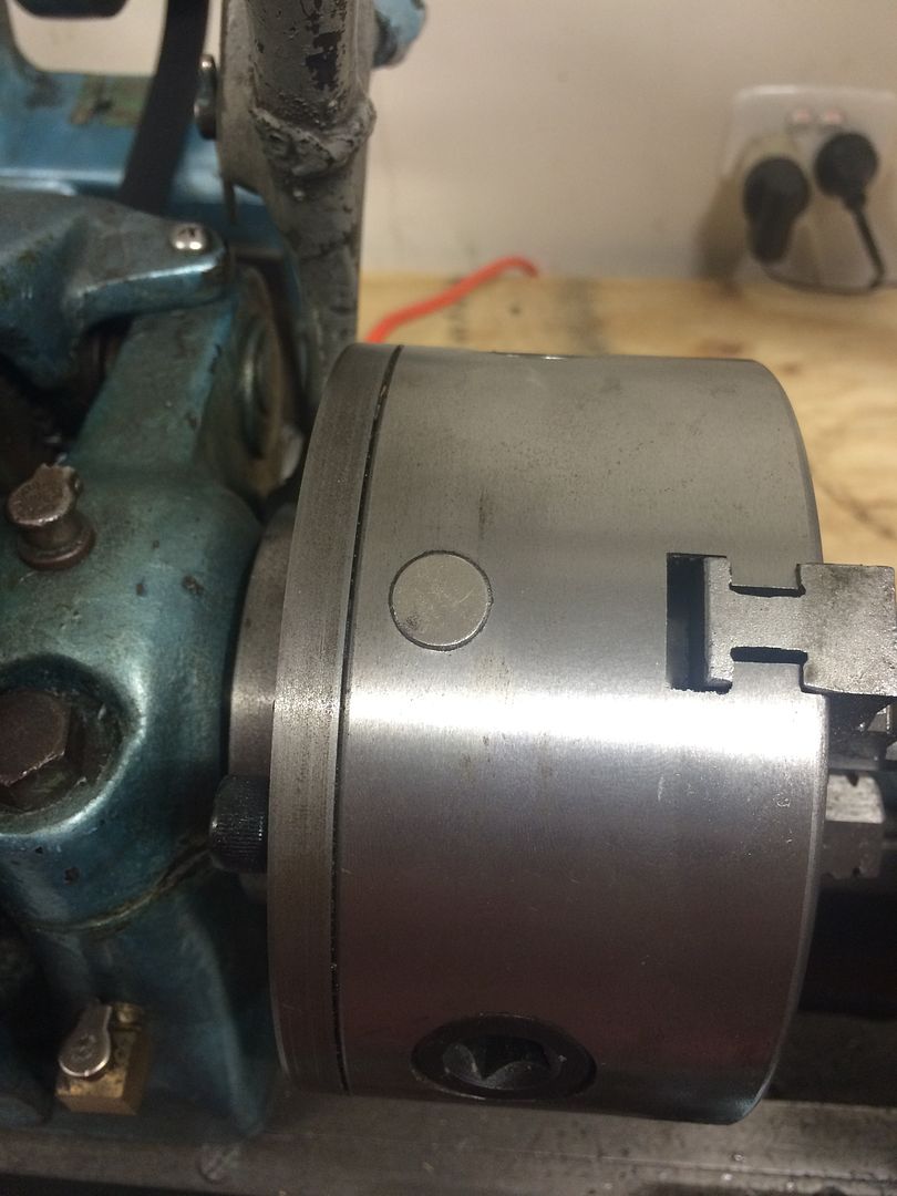
It reads off a magnet which I drilled a hole in my 3 jaw chuck and epoxied in the magnet:


An eBay job extraordinaire but it works perfectly. The adjustment on the dial works right down to 40 RPM so I almost never change the belts. Only thing I do sometimes is put it in back gear and lowest ratio for tapping or really slow work.

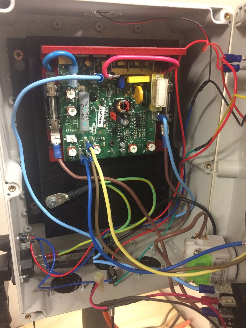
For those wanting a more stripped down view on the build here is inside the control box. It looks like a few wires but in essence it is very simple. You can see the DC controller (red part) is quite small actually. However the control box was sized off the heat sink it is attached to. Probably overkill from my end, especially with the fans etc, but better too much cooling than too little:


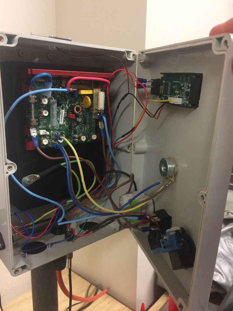
The wire for the black rotating motor switch is not connected here as the cable is a bit short with the door open. This view is so you can see the stuff in the door too. Box is hinged with a high tech sticky tape hinge ;) :


Here is how it looks when it's running (although not under its own power, I just turned the chuck by hand):

 
Awesome as usual.
A quick note to folks who don't travel much: OZ main house AC voltage is 240VAC (like most of the EU)
North American standard house voltage is 120VAC (usually somewhere between 110 and 120)
 
Bozz said:
Awesome as usual.
A quick note to folks who don't travel much: OZ main house AC voltage is 240VAC (like most of the EU)
North American standard house voltage is 120VAC (usually somewhere between 110 and 120)

Correct Bozz. Luckily the KB Electronics DC driver comes in a 240, 110 or a switchable input voltage model. I assume the output power of the motor would affected if you tried to drive a 240V motor on 110v.
 
most excellent write up! thanks a million for taking the time to do that. ill be following your setup closely when I get ready to switch mine. I think dc is the way to go. I really wanna put a dro on it as well, but baby steps....

Thanks again friend!
 
There's also the VFD route, especially for a mill or similar equipment that runs off 3 phase.
 
Correct. Actually VFD is probably a better option in the long run as I spent almost the same on my setup. The only reason for using the DC motor for me was because I didn't have enough room on the motor mount for a 3 phase motor plus I've heard there are some torque benefits to using a DC motor.
 
Back on bike talk. My exhausts have arrived from Megs!!!!!

Unfortunately I'm down in Melbourne for work so won't see them until tonight!

Also have had a few other bits and pieces arrive for the build.

Slowly progressing!

Will share pics and questions once I get home :)
 
Hopefully the build reinforces bad ass with my latest purchases. Some are mundane but clearly functional, some make my trousers do funny things!

First up?

Well it's not the most exciting purchase, but functional it certainly is. I was thinking of ways to attach my (planned) Alu seat pad to my seat and had settled on Velcro, but some eBay searching highlighted this product from 3M. It's a Velcro substitute that had a few advantages over the hook and sling material option:


The product is designed for outdoor use and has a very positive click as you push it together so I think it will work perfectly. Just need to get the seat finished before using it.

So having found a solution to attaching the seat pad to the seat I thought a little further and wanted a solution to make sure the seat pad was located in the exact correct location each time it was attached. Cue my next purchase:


How do I plan on using these? The idea was to weld in a couple of stalks on the seat pad pointing down. These would locate into these rubber grommets which would be located into the metal seat. I assume this would mean the seat would locate in the same place each time.

Next up I bought some of these:


Lastly I bought these:


This was a big gamble for me as I didn't know exactly how big they were going to be in real life, but to say I'm excited is the biggest understatement! I think these are going to look killer on the bike and the size seems PERFECT.

Unfortunately I cannot mount these on the bike as 1) they don't have mounts attached yet (see previous purchase) and 2) I don't have any exhaust hangers. However I was still excited to see how they would look pointing out the rear end of the bike, so I propped them up in the box to get a rough idea:


Oops! Something just happened in my pants. Thank god! This option was more expensive than the Yoshimuras I just sold.
 
Pretty pleased with myself tonight as I've finally managed to put my lathe to use and build a part from scratch. I'd bought some Alu round stock during the week in a few different diameters (6061 I think) and tonight I set to making a top hat bush for my throttle because it had ruined the last one trying to tap it out to M10 x 1.5 (for the cable adjuster).

First step was to drill and tap the stock. Then work on getting the external shape.

I was really happy with the finish I was getting as I had made some new HSS tools and with a bit of oil I was getting a pretty good finish, however the swarf coming off was getting a bit gummy on the stock.

Here's the part all done and ready for parting off:


Here it is against the original part:


It's held in place with a set screw. I probably could have done with about another 5mm on the part as the set screw is near the end, but it will do:


All mounted and looking pretty sweet. Actually like the silver contrast:

 
Back on the lathe tonight for a couple of projects. A stepped washer for the fan on my lathe motor (not documented) and this:


I had purchased a new MT2 dead centre for the lathe for an upcoming rear engine mount bush part and annoyingly it wouldn't eject from the tail stock as the shaft was too short. So I grabbed some crappy steel rod from an old treadmill and set to making an extension. I left a post on the part that would locate in a hole on the end of the dead centre with a slight interference fit.

Quick check to make sure it all worked and then I epoxied it in:


The steel is really crappy and doesn't machine very well but it will do and I will tidy up the end on the bench sander once the 2 part epoxy has gone off.
 
In the vein of trying to knock small items off the list to keep the build progressing, tonight I thought I would tackle the engine mounts. I had an issue in the upper rear mount in that my new CNC mount was too thick to allow the original bolt:


I wanted to see if there was an option in stainless however there wasn't other than a completely threaded one for a lot of money.

So I decided to make my own. I bought some 10mm stainless rod and set to threading the end for a nut to be welded on:


I knew the SS would work harden but threading it was a total pain. In the end I had to resort to doing a few passes with the die one way, then flip it to progress it further down the rod. Slow going but in the end it worked. I used the lathe to hold the rod:


The plan is to weld the nut on the end and then face it off on the lathe to tidy it up:


Next I turned my attention to the spacer for the same engine mount:


This was an easy job and quickly made out of Alu. Meant I got to try out my new upgraded dead centre:


Here is the original setup vs the new. I still have a lot of length on the bolt that I need to trim and try and thread again:


Next up I shortened the spacers for the right hand side engine mount and bolted it all together:


Turns out the threads on the right hand side mount (rear ones) are not M8 as per the bolts as originally planned. So I'll need to get some longer bolts for those vs trying to use what I have. Also the holes are not perfectly lined up, so it will allow me to get a bit of wiggle room where I need it as the motor is in there pretty bloody tight at the moment:


Lastly I bolted in the front engine mount. Again the bolt holes are a little misaligned so I couldn't get a bolt through the top hole, but I'm thinking I can drill them out 1 size larger to get the extra clearance I need:


All done and starting to look good. The CNC stuff really finishes off the motor and makes it look like a serious bit of kit:


Next job for the mounts will be to get them anodised along with a load of other Alu bits, to protect them from the elements.
 
Back
Top Bottom