Help me understand this wiring diagram

mickey_7106

New Member
i had a difficult time figuring out why my tail light wouldn't work. i understand how all these wires connect to the bike but im having a hard time understanding how they get power.

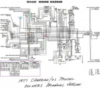
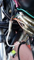
Background info i installed a new phase 7 led headlight with bucket. There wasn't enough slack in the wires for me to stuff them back in the bucket so i left them out. somewhere in the process i lost the tail light (brake still worked), gauge lights, oil and neutral indicator. Yesterday i unplugged every connector that meets at the front forks and started fresh making sure everything is plugged where it should be. the only thing that was different was that my front turn signals only have two wires and now i have day time running lights ( They didn't light up before unless to turn). looking at this diagram i realized that they were originally 3. After everything was plugged in everything else worked exept the tail light. after a lot of testing i realized there was a small "jumper" wire that i had no where to plug it to according to this diagram. i plugged it to the front brown to a black and my tail light can on! i spent hours tracking this down and it was a simple "fix"


So i see that battery power from fuse goes to the keyed ignition switch, Which then powers black, Brown/white and brown right? i couldn't get any power from brown so does that mean the ignition switch needs repair or be replaced? i Checked for conductivity from the front brown wire that shouldn't be plugged to anything all the way to the contact point of the bulb and there was no break in the line.

Check diagram i posted
1. what do those dots mean? Solder points?
2. is that a diode?
3. There's a P on my ignition but i cant turn the key to that position. Does that translate to PA on this diagram? whats it for?
4. how can i read these boxes to interpret them better?
 

Attachments

  • WD400771.jpg
    WD400771.jpg
    1.4 MB · Views: 232
  • 20160405_190012.jpg
    20160405_190012.jpg
    874.8 KB · Views: 205
  • 20160405_191951.jpg
    20160405_191951.jpg
    1.1 MB · Views: 210
  • 20160405_192001.jpg
    20160405_192001.jpg
    1 MB · Views: 209
BTW is there a reason for all these wires to be wrapped in tape and not wire loom? and lastly the running lights turn off when i switch to high beam, is that normal?


TIA
 
1.) Dots mean a join of some sort. Usually soldered, sometimes crimped, sometimes a connector.
2.) Probably a spare connection for some device used in another region.
3.) They're the same setting. PA is the Parking light (small bulb in the headlight bucket and the tail light).
4.) Circles with lines mean the functions are joined in that position. For instance, in the RUN position, the ignition switch connects BAT and IG as well as TL1 and TL2.
 
OK, being a motor mechanic for 26 years I'll try and help.

1.what do those dots mean? Solder points? - Yes they are joins, but most likely brass crimp connections on Jap motorcycles.

2. is that a diode? - No. This looks like an earth point, black is traditionally the earth return on Jap bikes. To double check, see if there are any earth points on the loom, and check the wire is black.

3. There's a P on my ignition but i cant turn the key to that position. Does that translate to PA on this diagram? whats it for? - P on the ignition is for parking lights, i.e. turn it to this position and the parking (some times known as side lights) come on. This position is usually after the steering lock position, therefore to get the ignition to this point, you need to have the steering lock on. In P position the key should be able to be removed from the ignition barrel. PA is the parking light feature.

4. how can i read these boxes to interpret them better? - Not sure what you mean here?

As for some of the loom being tapped and outside the main loom, this isn't uncommon on Jap bikes.

Why have connected the earth to the brown wire, the brown link on the copy of the wiring diagram. Just because a connector isn't connected doesn't mean it needs to be, remember these bikes are for worldwide markets and not all have the same lighting requirements/options. This brings me onto the question about your running lights, this isn't a feature in the UK, therefore I cannot be certain, but I would suggest the running lights in the turn signals (indicators) need to stay illuminated at the time the lights are on. I think the link you've added may be the issue here.
 
Just looked again, your jumper wire is earthing the turn signals, hence giving you running lights.
 
Karlloss said:
2. is that a diode? - No. This looks like an earth point, black is traditionally the earth return on Jap bikes. To double check, see if there are any earth points on the loom, and check the wire is black.

On Hondas, black is power. The other manufacturers use black, black/white, and black/yellow for ground. Yamaha, Suzuki, and Kawasaki, respectively.
 
Sonreir said:
1.) Dots mean a join of some sort. Usually soldered, sometimes crimped, sometimes a connector.
2.) Probably a spare connection for some device used in another region.
3.) They're the same setting. PA is the Parking light (small bulb in the headlight bucket and the tail light).
4.) Circles with lines mean the functions are joined in that position. For instance, in the RUN position, the ignition switch connects BAT and IG as well as TL1 and TL2.

In essence the same as I was saying. I'm not as quick at typing!
 
Karlloss said:
Just looked again, your jumper wire is earthing the turn signals, hence giving you running lights.

Brown is the tail light and black is power, so the jumper is just passing power on to the tail light.
 
Sonreir said:
Weird, right?
That threw me the first few times I worked with them.

Yeah, so much so, I'm going to take a look at my Honda CRM 250 for earth colours. Having mostly worked on Yams, I made the assumption all were similar.

Every day's a school day :D
 
Thanks, My bike didn't come with the small bulbs on my headlight or tail light so im going to assume that wasn't an option for this bike. Could that be the reason why i cant switch the key to the P position?

Sonreir said:
3.) They're the same setting. PA is the Parking light (small bulb in the headlight bucket and the tail light).
4.) Circles with lines mean the functions are joined in that position. For instance, in the RUN position, the ignition switch connects BAT and IG as well as TL1 and TL2.
What about for the other switches? is there a place where i can find definitions for W,L, R, P(f), PL, PR etc?


Karlloss said:
OK, being a motor mechanic for 26 years I'll try and help.

4. how can i read these boxes to interpret them better? - Not sure what you mean here?

How can i read the arrangement boxes on the lower left of the diagram? the ignition arrangement was easy to figure out aside from the doted circles. i don't know what that's supposed to do.
 
mickey_7106 said:
What about for the other switches? is there a place where i can find definitions for W,L, R, P(f), PL, PR etc?
How can i read the arrangement boxes on the lower left of the diagram? the ignition arrangement was easy to figure out aside from the doted circles. i don't know what that's supposed to do.

Circles with lines mean the functions are joined in that position. For instance, in the RUN position, the ignition switch connects BAT and IG as well as TL1 and TL2.
 
Back
Top Bottom