
Many of you know that I've been tinkering with this idea for a while. The Honda twins don't often generate enough power at idle, which really kinda cramps my plans for an EFI system at some point in the future.
So... time to solve the problem of anemic charging. When it comes to alternator/generators, three things affect the output.
[list type=decimal]
[*]Strength of the magnet in the rotor
[*]Number of windings in the stator (affects voltage)
[*]The thickness of the wire used in the windings (affects current)
[/list]
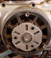
The easiest electrical option would be just to increase the strength of the magnets within the rotor. Unfortunately, new rotors would be difficult to manufacture and I don't want to get into the intricacies of milling out rotors to attach new magnets. We can still revisit this if we need to, but I decided to table it for now.
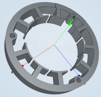
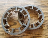
So these leaves us with modifying the stator in some way. We made a couple of adjustments here. First, we eliminated three of the six mounting holes. This frees up room for more copper. Ultimately, the voltage and the current are going to be sort of a self-balancing situation, due to Ohm's law and the implemented voltage regulator, so we'll tweak those variables later, if needed. Basically, more copper = more power. Whether it comes as current or voltage, we'll worry about later. "Try it and see" is where I'm working from right now.
Additionally, we've changed the number of poles on the stator from six to nine. By going with three groups of three, we can more easily implement a three phase setup. In a single phase setup, there are two output wires from the stator. Each wire represents one end of the circuit, and as the magnets approach, and then depart, the center line of the windings, voltage increases towards a maximum positive amplitudes and then reverses direction and reaches a maximum negative amplitude.
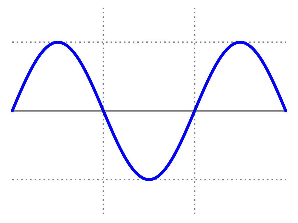
Three phase works a bit differently. There are three output wires from the stator. Each of these wires represent one end of a circuit, with the opposite end of each of the three wires, joined together into what's known as a star configuration. You can also wind three phase as a delta config, but I've opted for star since it's a little easier. Functionally, I'm not expecting a big difference between the two, but we can experiment later if this first go doesn't work out. Anyway... because of the configuration of the poles and the windings, there is never a point where zero power is being produced by the alternator. This should provide us with steadier output from the alternator and hopefully help overcome the charging issues from which these machines suffer.

That's the idea. Looks like everything is fitting up OK, so time to start winding copper...
So... time to solve the problem of anemic charging. When it comes to alternator/generators, three things affect the output.
[list type=decimal]
[*]Strength of the magnet in the rotor
[*]Number of windings in the stator (affects voltage)
[*]The thickness of the wire used in the windings (affects current)
[/list]
The easiest electrical option would be just to increase the strength of the magnets within the rotor. Unfortunately, new rotors would be difficult to manufacture and I don't want to get into the intricacies of milling out rotors to attach new magnets. We can still revisit this if we need to, but I decided to table it for now.
So these leaves us with modifying the stator in some way. We made a couple of adjustments here. First, we eliminated three of the six mounting holes. This frees up room for more copper. Ultimately, the voltage and the current are going to be sort of a self-balancing situation, due to Ohm's law and the implemented voltage regulator, so we'll tweak those variables later, if needed. Basically, more copper = more power. Whether it comes as current or voltage, we'll worry about later. "Try it and see" is where I'm working from right now.
Additionally, we've changed the number of poles on the stator from six to nine. By going with three groups of three, we can more easily implement a three phase setup. In a single phase setup, there are two output wires from the stator. Each wire represents one end of the circuit, and as the magnets approach, and then depart, the center line of the windings, voltage increases towards a maximum positive amplitudes and then reverses direction and reaches a maximum negative amplitude.
Three phase works a bit differently. There are three output wires from the stator. Each of these wires represent one end of a circuit, with the opposite end of each of the three wires, joined together into what's known as a star configuration. You can also wind three phase as a delta config, but I've opted for star since it's a little easier. Functionally, I'm not expecting a big difference between the two, but we can experiment later if this first go doesn't work out. Anyway... because of the configuration of the poles and the windings, there is never a point where zero power is being produced by the alternator. This should provide us with steadier output from the alternator and hopefully help overcome the charging issues from which these machines suffer.
That's the idea. Looks like everything is fitting up OK, so time to start winding copper...
")
 said:
said:


