Interior Drawing of Keihin VB42a Off a 1980 CB750

SimonDanger

New Member
Ok, here's the thing...I'm newish here and it appears I'm also a bit of a masochist. I seem to like the almost woman-like complexity and, at times, contradictions, of the EPA-inspired Keihin CV carburetor. It intrigues me, so I dig deeper, ever trying to untangle the mystery of her inner thoughts, feelings and emotions ;)

It is these of which I speak:


I've always taken apart carburetors, regardless of their intimidating appearance, and managed to get a few back together as well. I just like the simple yet complex mechanics of these things. Even though I have been urged to never, ever, dispatch with the imperial airbox that is the black molded plastic lung through which these girls breath, I nonetheless charge head-long into the shadowy jungle passages in search of the heart of darkness. The horror; oh the horror. Inasmuch as I can, I want to take this forensic knowledge of this carb and try to tune my foursome into a smooth growl, from idle all the way thru WOT, by re-jetting my airboxless Keihins on my 750.

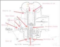
Having read endlessly everywhere I can find (this board, the interwebs, my service manual) and having disassembled my girls a few times already, I have yet to find a single drawing of just what the specific ports & jets in the Keihin VB42a look like. Sure, there are exploded views of the various parts that are specific to that model, and then there are the crude mspaint drawings showing the dumbed-down view of a generic carburetor. But no mechanical drawings or spec sheets of this carb...so I took matters into my own hands and drew this:


I make no assertions as to the quality of the above drawing...

It is my intention to seek the council of the experts here who have - shall I say - an intimate relationship with this carb and direct me as to how I might modify my drawing to more accurately reflect this carb's design. I'm most interested in where in the venturi the ports/jets lie in linear relation along the air-flow channel. If you see any glaring omissions/additions, please point them out. If you happen to know where a better drawing is, please post its link. 8)

Thanks
 
Nicely started!
You appear to be missing the Air Cut-off valve.
Are you after a scale drawing or a flow chart/logic diagram?
You seem to be sort of somewhere in the middle of these...
 
Bozz said:
Nicely started!
You appear to be missing the Air Cut-off valve.
Are you after a scale drawing or a flow chart/logic diagram?
You seem to be sort of somewhere in the middle of these...

As I understand the air cutoff circuit, it richens up the mixture on deceleration in order to eliminate back-fires. Does it co-opt an existing port/jet, or does it have a dedicated one of it's own? Scale, not so much; really trying to get my head around the accumulation of atomized fuel as a volume of air passes thru the unit (sounds more like the logic diagram). I'm also mildly curious about the very turbulent and, it seems to me, quite eddy-prone air flow around the choke and throttle plates and the vacuum piston pig in the center!
 
The vacuum in the upper chamber is created by the velocity of the air past the bottom of the slide. The yellow line to the chamber from is atmospheric, by your drawing, and does not create the vacuum....

Not sure where that yellow line feeds, but usually the front vent feeds under the piston, but you have another one there. Think you may have them mixed up. Some of the atmospheric pressure under the piston feeds air through jets for the emulsifiers.

I'll look to see if I have any info when I am home.
 
mydlyfkryzis said:
The vacuum in the upper chamber is created by the velocity of the air past the bottom of the slide. The yellow line to the chamber from is atmospheric, by your drawing, and does not create the vacuum....

Not sure where that yellow line feeds, but usually the front vent feeds under the piston, but you have another one there. Think you may have them mixed up. Some of the atmospheric pressure under the piston feeds air through jets for the emulsifiers.

I'll look to see if I have any info when I am home.

Glad you pointed that out! I was assuming the crescent-shaped opening in the fresh air entrance was how a vacuum was produced on the upper surface of the piston, but it didn't make sense to me being where I would intuitively think a higher pressure would be generated...


I guess I always assumed these were vacuum ports, as anything inside the carburetor would theoretically be at a lower air pressure than the surrounding atmospheric pressure, ie Bernouli. Where do these inlets go when they disappear inside?
 
airflow is from right to left in pic.
Primary and secondary main jets are labeled backwards.
Pilot circuit is fed from primary main jet. (don't see pilot jet anywhere?) The passage you have marked (slow/choke) is in completely wrong direction
Air cut valve is a separate passageway connected to primary main jet, in effect you have 2 airways in, one closes on decel (easier to shut off air than add more fuel and the effect is the same)
Accelerator pump on #2 float bowl
There is no enrichener circuit, that's on Mikuni, it's a bypass passage for when throttle plate starts to open (may be 3~5 drillings)
The 'slot' at top is slide lift holes, exits UNDER slide not on top, vacuum comes through drillings in slide
The drilling to right side probably goes to air cut valve?
I'm pretty sure genuine Honda manual has line drawing of circuits? (been a while since I looked at 750/900 carbs)
 
crazypj said:
airflow is from right to left in pic.
Primary and secondary main jets are labeled backwards.
Pilot circuit is fed from primary main jet. (don't see pilot jet anywhere?) The passage you have marked (slow/choke) is in completely wrong direction
Air cut valve is a separate passageway connected to primary main jet, in effect you have 2 airways in, one closes on decel (easier to shut off air than add more fuel and the effect is the same)
Accelerator pump on #2 float bowl
There is no enrichener circuit, that's on Mikuni, it's a bypass passage for when throttle plate starts to open (may be 3~5 drillings)
The 'slot' at top is slide lift holes, exits UNDER slide not on top, vacuum comes through drillings in slide
The drilling to right side probably goes to air cut valve?
I'm pretty sure genuine Honda manual has line drawing of circuits? (been a while since I looked at 750/900 carbs)

Jackpot! Thanks crazypj, that's exactly what I'm looking for. I'll draw up another rendition with your changes tomorrow. Part of what I've noticed when reading about these types of carbs is the nomenclature gets used differently in many places. Pilot, slow, idle and choke to name just a few. I have not been able to find the circuit drawings in all the on-line versions I've read.
 
Pilot, slow, idle are all the same thing.
Choke is used wrong on many vehicles (fuel injected don't have choke, Mikuni generally don't have choke)
The Honda almost always have a choke flap with literally chokes the airflow on airbox side of carb creating higher vacuum on fuel circuits
 
Here's a cutaway of the CB350 Carb...It is a little different, but mostly the same....
 

Attachments

  • CV Carb Cutawayarked up.JPG
    CV Carb Cutawayarked up.JPG
    101.6 KB · Views: 3,826
PJ is correct. Yellow "vacuum" comes through the slide and atmospheric pressure comes from the bean slot at the top of the inlet.

You also need to add the air passages. See if you can find a copy of the Honda Motorcycle Carburetor Manual dated 1975 or Fuel manual dated 1986. The first is available as a pdf download http://minus.com/lbrGNSbzU9N4UN
 
Screwed the pooch with all my links on the first try so here's the second attempt.

Thanks Teaser for the link; some good drawings I hadn't discovered yet. Also thanks to MildlyCrazy (?) for the drawing...yet another I was not able to find in the ethers. Interesting that I thought the needle and its jet were the "main" fuel delivery system, but it appears from further reading and the comments posted that the "primary" system is down-stream from the secondary needle system.

Here's the latest admittedly crude rendition, with a change in colors. Blue is fresh air, yellow is liquid fuel, green is the fuel/air vaporized mixture of the two. (Also note that the venture does not diverge after the vacuum piston, as was originally drawn in the first drawing.)


I still don't fully understand why there are both a primary and secondary main air jets, and primary and secondary slow air jets, so I really just drew them in where I figured they made the most sense. I also don't know where to put the air cut-off circuit. Let me know if I'm getting close.

On a side note I synchronized the bank yesterday and went from this...


To this...

http://s1263.photobucket.com/user/SimonDanger/media/F777CD45-8C18-4BE0-996E-E1FC00ADCF90-2799-0000017B59A1DABC_zps3c72e795.mp4.html

What a difference this made in her attitude. Great low and mid range responsiveness, can get up to 70 mph no problem, but on WOT she bogs for more fuel. This is where I plan to rejet to a larger Primary Main Jet (?).
 
You need a third jet, the pilot is a separate circuit but is fed from primary main jet
Air cut valve will go on your secondary main jet air passage
#3 will go lower, into pilot jet emulsion tube
I still have no idea why you drew #9? there isn't any fuel delivery except accelerator pump on the airbox side of carb

I'll see if I can find the correct drawings to explain air cut valve, they have been fitted since 1977 but very few people seem to understand how they work or what they do
 
Back
Top Bottom