Bought a Universal switch from Speed Moto Co for my 82 CB750K. It came with no wiring diagram to tell what wires do what.
This is the description of the switch I bought:
Simple, clean switch that combines 2-wire kill switch (positive) and starter button (momentary). Also great for custom builds, drag bikes, race bikes etc. For 7/8" bar. The switch housing is only 7/8" wide so narrow enough to fit between a push-pull race throttle and the brake lever.
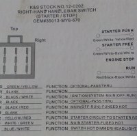
It has a yellow with red stripe, two black with white rectangles, one black with red stripe, one blue with white stripe, and two black with green stripes.
This is what I have gathered on the CB wires.
Black - Power to the kill switch
Black/white - Power from the kill switch to the coils
Black/red - Power in to the headlight cutoff
Blue/white - Power out from the cutoff to the headlight (the cutoff turns the headlight off when you're using the starter motor)
White/green - Power to the brake switch and the horn
Green/yellow - Power from the brake switch to the brake light
Yellow/red - Power from the starter button to the solenoid
Black - Power from the harness to the starter button
Anyone possibly know what goes to what? I'm an idiot when it comes to wiring. I have e-mailed the retailer a couple times to see if they have a diagram on it, but no response.
This is the description of the switch I bought:
Simple, clean switch that combines 2-wire kill switch (positive) and starter button (momentary). Also great for custom builds, drag bikes, race bikes etc. For 7/8" bar. The switch housing is only 7/8" wide so narrow enough to fit between a push-pull race throttle and the brake lever.
It has a yellow with red stripe, two black with white rectangles, one black with red stripe, one blue with white stripe, and two black with green stripes.
This is what I have gathered on the CB wires.
Black - Power to the kill switch
Black/white - Power from the kill switch to the coils
Black/red - Power in to the headlight cutoff
Blue/white - Power out from the cutoff to the headlight (the cutoff turns the headlight off when you're using the starter motor)
White/green - Power to the brake switch and the horn
Green/yellow - Power from the brake switch to the brake light
Yellow/red - Power from the starter button to the solenoid
Black - Power from the harness to the starter button
Anyone possibly know what goes to what? I'm an idiot when it comes to wiring. I have e-mailed the retailer a couple times to see if they have a diagram on it, but no response.