Open Source DIY Electronic Ignition

Fuck it... I've got too much time into this one to quit with the finish line being (seeming?) so close.

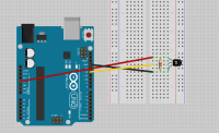
I've made a swap over to Arduino. The control libraries are awesome and support it good. I've heard their libraries do have a bit of overhead, but I'm hoping at four million operations per second, it won't matter too much.

Code:
const int MIN_RPM = 800;
const int MAX_INDEX = 205;
const int DWELL = 1500;
const int COIL1 = 4;
const int COIL2 = 7;
const int SENSOR1 = 2; //idle sensor
const int SENSOR2 = 3; //cam sensor

bool triggered = false;
long lastDuration = 0;
unsigned short currentIndex = 0;

unsigned int RPMS[MAX_INDEX];
unsigned int HALVES[MAX_INDEX];
unsigned int DELAYS[MAX_INDEX];

///Build all of the values in the arrays based on our starting RPM and initial and final advance
///Redline is (MAX_INDEX-1) * 50 + MIN_RPM
void calculateArrayValues()
{
	double startRPM = MIN_RPM; //use a double for increased precision in the calculations
	int startAdvance = 18; //18 degrees of advance coming on at 800 rpm
	int endAdvance = 38; //total advance of 38 degrees
	int endRPM = 4000; //total advance to be achived at 4000 rpm
	int hallAdvance = 180; //assume sensor is 180 degrees advanced from TDC
	double slope = abs(endAdvance - startAdvance)/abs(endRPM - startRPM); //function to calculate linear advance is y = mx+b where m = (y1-y2)/(x1-x2)
	int intercept = startAdvance - (startRPM * slope); //intercept is b from above formula

	//build the arrays, 50 rpm at a time
	for(int i = 0; i < MAX_INDEX; i++)
	{
		double usPerDegree = 1000000 / (startRPM / 60) / 360;
		double advance = startRPM * slope + intercept; //use our function to calculate the advance
		int advanceDelay;
		
		if(startRPM >= endRPM) //if our current RPM is >= the to ending RPM, just use 38 degrees
		{
			advance = 38;
		}
		
		advanceDelay = ((hallAdvance - advance) * usPerDegree) - 1500; //calculate the time we wait before picking up the sensor and starting the spark process on the coil(s)
		
		DELAYS[i] = advanceDelay;
		HALVES[i] = usPerDegree * 180; //we're on a 180 twin, so calculate the delay between the first coil (left) and second coil (right) firing.  This way, we only need one pickup.
		
		startRPM += 50; //increment the RPMs for the next iteration
	}
}

///Fires a coil by grounding the selected pin, waiting the dwell period, then ungrounding it
void dwellAndFire(int pin)
{
	digitalWrite(pin, HIGH); //ground the coil
	delayMicroseconds(DWELL);
	digitalWrite(pin, LOW); //trigger the coil
}

///Fires both coils with the currently mapped delay values
void fireWithDelays()
{
	delayMicroseconds(DELAYS[currentIndex]);
	dwellAndFire(COIL1);
	delayMicroseconds(HALVES[currentIndex]);
	dwellAndFire(COIL2);
}

///Interrupt for the idle sensor.  At RPMs less than RPMS[0], use this sensor to immediately trigger the coil(s) with no delay.
///This sensor will be located around 6 to 10 degrees BTDC
void idleSensor()
{
	if(lastDuration > RPMS[0])
	{
		int coil2Delay = (lastDuration / 4); //engine spinning slower than our map, calculate delay for second coil (divide by four is 90 degrees of rotation)
		
		dwellAndFire(COIL1); //fire left coil
		delayMicroseconds(coil2Delay); //wait 180 degrees
		dwellAndFire(COIL2); //fire right coil
	}
}

///Interrupt for the "running" sensor
void camSensor()
{
	triggered = true;
}

///Set the pins appropriately, calculate the values we'll be using, and then attach the interrupts
 void setup()
 {
	 pinMode(COIL1, OUTPUT);
	 pinMode(COIL2, OUTPUT);
	 pinMode(SENSOR1, INPUT);
	 pinMode(SENSOR2, INPUT);
	 
	 calculateArrayValues();
	 
	 attachInterrupt(0, idleSensor, RISING); //idle sensor interrupt
	 attachInterrupt(1, camSensor, RISING); //cam sensor interrupt
 }

///If we pickup a trigger from the running sensor, adjust the timing map and then fire the coils
 void loop()
 {
	 if(triggered)
	 {
		 noInterrupts();  //turn off interrupts
		 triggered = false;
		 lastDuration = (micros() - lastDuration); //number of microseconds since last rotation
		 
		 if(lastDuration > RPMS[MAX_INDEX]) //not past redline, OK to fire spark
		 {
			if(lastDuration < RPMS[0]) //cam sensor (not idle sensor) handling spark check index
			{
				if(lastDuration < RPMS[currentIndex]) //engine speed increasing
				{
					currentIndex++; //jump to the next value in the array
				}
				else if (lastDuration > RPMS[currentIndex]) //engine speed decreasing
				{
					currentIndex--; //drop to the previous value in the array
				}
				
				fireWithDelays();
			}
		 }
			 
		 interrupts();  //turn interrupts back on
	 }
 }

So there we have it. Running code for a 180° twin. Totally untested.

What I really like about this setup() function approach over my spreadsheet is that in the long term, I can add an interface to the Arduino and make it programmable on the fly. Buttons to adjust initial and final timing and then recalculate the whole lot... Save the values to the EEPROM, reset the chip, and we have a new timing map. I guess I just need someone to machine me a rotor to fit over my cam, now, and then I can get testing. ;D
 
Simplistic - but keep pluggin away - :)
I went a slightly different approach - Follow the sigature link if you're interested.

Is there a particular bike that specifically needs attention ?

Regards
Ray-San ( aka Rayman)
 
Sonreir said:
I've made a swap over to Arduino.

Awesome! Welcome to the Atmel camp! Arduino is Atmel micro based.

I was wondering if the Pic is in circuit programmable. Over at work, I only have the PIC programmer for the whole micro into a socket. The Atmels can be programmed on board (6 pins). Take a peak at the forum (http://www.avrfreaks.net/). Also, check out the little programmers you can build:
http://fabiobaltieri.com/2011/09/02/usb-key-avr-programmer/
usbasp.jpg


I was using a ATMega168 (28 pin, 23 IO) but it's bit overkill in the size & I/O department. So, I'll be looking into an ATTiny85-20 (8 pin, 6 IO). 8K Flash, eeprom, ADC, 20Mhz.

Keep up the good work. I'll try to help as I get time. Swamped here at work as I'm still the only engineer.

Ray-San: Looks like some cool stuff you got there. [edit] Matt and I working on the CB360 and CB350 twins.

You can see and hopefully appreciate all the time and effort it goes into software programming.

Eric
 
The Arduino is pretty simple to code and even easier to upload. The Uno comes with a USB connector that allows programming right on the board as well as being a source of power. The software from Atmel for the USB to serial communications was a snap to install and worked without any further configuration. Still working on getting it setup for Atmel Studio, but it works in Sketch, no problems.
 
If you run into a wall, drop me a pm. I use studio with Atmel USB "blue box" programmer. Most of the basic stuff was easy. I had the tough time learning the ADC and I have yet to learn all the features, which I plan to do.
 
kopcicle said:
http://xs650temp.proboards.com/thread/7899

Jus sayin ;-)

Now if you want to start looking into fool infection I'll be listening

~kop

That'll be next, kop, just as soon as I get spark sorted out.

The plan is to use some EX650 throttle bodies. They come with MAP, TPS, and injectors and can be found on eBay for under $70. Combined with a Bosch 0580254911 fuel pump, I should be good to go. The tricky part will be working out a fuel map. I have a pretty good understanding of how revs affect fuel usage, but I also need to take into account throttle position and manifold pressure and I only have the basic gist of that... Got some reading to do, methinks.
 
the best way to do this is with an optical encoder, that way you're not trying to write code to predict the advance on an accelerating or decelerating crank as with a magnet. you can get 512 position wheels and encoders for not too much money, and that way you've got a real lock on crank position. I've played with the single magnet with a pic and got it working, but acceleration rate can change quite a bit on the crank between sensing the magnet, so while it may be accurate at cruising, could be problematic under acceleration where it really counts. cyclex also came to that conclusion and uses an optical wheel with their unit
 
I've not heard of that kind of hardware before. Do you have a link I could take a look at? I Googled "512 position wheel" and didn't come up with much...

Thanks in advance.
 
RCC is correct - the best way if you're going to replace the pickup sensor arrangement is to use a multitoothed magnet or optical wheel - this allows you to get an accurate estimate of acceleration or decel from pulse to pulse. Optical sensors can suffer a bit from oil mist problems depending where the sensor is located in various engines, so hall effect / magnetic may be better in such situations.

With a simple single/ dual edge magnet - you need to allow for firing at the base timing if the engine is decelerating quickly - in practice it doesnt hurt but can result in a bit more exhaust popping on overrun.

The biggest Issue I find with the "single point" sensing is idle smoothness - if you've got a 90 degree v twin with a light flywheel - the speed varies significantly around the engine rotation -

Designing from scratch - go multitooth if possible -
Designing to work with existing pickups - you're stuck with the factory arrangement (and this is where I came in :))

Regards
Rayman
 
this is awesome, I'll be following this thread to see where the project goes.


I'm no electronics wiz, but I have an open source LED flashlight that uses Arduino. It's fantastic.
 
Sonreir said:
I've not heard of that kind of hardware before. Do you have a link I could take a look at? I Googled "512 position wheel" and didn't come up with much...

Thanks in advance.

I've got one in my shop, I'll get you a part number... I think there are multiple optical sensors in the pickup too, so with some programming you could actually get higher resolution than the 512, but for all purposes ignition, it wouldn't need it

my bad, 500cpr

630-HEDS-9140-A00
630-HEDS-5140-A11
 
That's very good idea. I was thinking that in the back of my head that a single point position will only update every rev. Now, you'll have to account for more inputs on the micro. Here at work, we have a 12 bit encoder >>> good for 4096 discrete positions (2^12). I ran out of inputs and can only use 11 bits but this was still good for 2048. Although, it was split into two 180 sectors.

512 position encoder requires 9 bits (2 ^9) or 9 inputs to properly decode it. Make sure in your code to not use normal binary counting. Use Gray code. It counts with only one bit difference between each count. Otherwise, you will get noise due to misinterpretation. For example, you can't simply count from 0001 to 0010, since two bits change at once. In the micro world, you can only do one step or bit at a time. It will actually do this > 0001 > 0000> 0010 or it will do 0001 > 0011 > 0010. That intermediate step will cause the "noise". So, use grey code.
 
Got some A1120LUA-T Hall sensors on the way to my doorstep.

Working on the math to calculate acceleration and take that into account for my timings... Not sure if it's feasible with only one or two pickups, but we'll find out!
 
Proof of Concept has been completed on the Arduino Uno.

Very simple code just to read the Hall sensor to see if the magnet is close and then turn the LED on when it is or off when it is not.

Code:
const int hallPin = 12;     // the number of the hall effect sensor pin
const int ledPin =  13;     // the number of the LED pin

int state = 0;          // variable for reading the hall sensor status

void setup() {
  pinMode(ledPin, OUTPUT);      
  pinMode(hallPin, INPUT);     
}

void loop(){
  // read the state of the hall effect sensor:
  state = digitalRead(hallPin);

  //states are reversed due to pull up resistor... LOW is magnet sensed
  if (state == LOW) {     
    digitalWrite(ledPin, HIGH);  //LED on
  } 
  else {
    digitalWrite(ledPin, LOW); //LED off
  }
}

Simple diagram attached. Also... quick vid detailing the results.

http://www.youtube.com/watch?v=8UgXgUjai7w
 

Attachments

  • hall poc.png
    hall poc.png
    94.1 KB · Views: 855
Looks good! Next, test out loop timing. Do you have an oscilloscope to measure your pulse widths? How much was that Uno? You can buy just a micro for a couple dollars.
 
No scope. :(

The Uno came in a kit with a bunch of microswitches, LEDs, resistors, diodes, etc.... Even came with a remote control and some LED 7-segment displays... $25 for the whole thing. I'll probably swap over to a Micro or a Mini for the "real thing", but the Uno is a great test bed. Plugs right into my PC and I can use test leads in all of the sockets.
 
Ok, when u get a micro, consider an Attiny85. I have that micro & plan to develop code on that micro. If we want to co-develop code, it has to be the same micro & circuitry. It makes for easier portability. I can verify timing on my side. I already have working (kinda-sorta) core code (on the Atmega) but we can start from scratch if u want.
 
Back
Top Bottom