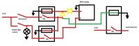
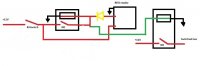
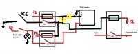
I would at least put another diode after the one you have in the diagram, but as it feeds down to power the other circuits. That way the RFID unit upon sending the signal is only powering that one relay, otherwise you could fry the output (don't think it can do more than a few mA).
As for the buzzing, does that happen even after the brake switch is released or does everything shut off when it's released? Because I could see a timing issue with the RFID sending its output which will open up the brake switch relay, causing the RFID unit to get powered off. The diode actually might help that since the brake switch relay will not get powered up until the top relay is fully powered up and closed. Maybe?
As for the buzzing, does that happen even after the brake switch is released or does everything shut off when it's released? Because I could see a timing issue with the RFID sending its output which will open up the brake switch relay, causing the RFID unit to get powered off. The diode actually might help that since the brake switch relay will not get powered up until the top relay is fully powered up and closed. Maybe?