Follow along with the video below to see how to install our site as a web app on your home screen.
Note: This feature currently requires accessing the site using the built-in Safari browser.
We noticed you are blocking ads. DO THE TON only works with community supporters. Most are active members of the site with small businesses. Please consider disabling your ad blocking tool and checking out the businesses that help keep our site up and free.
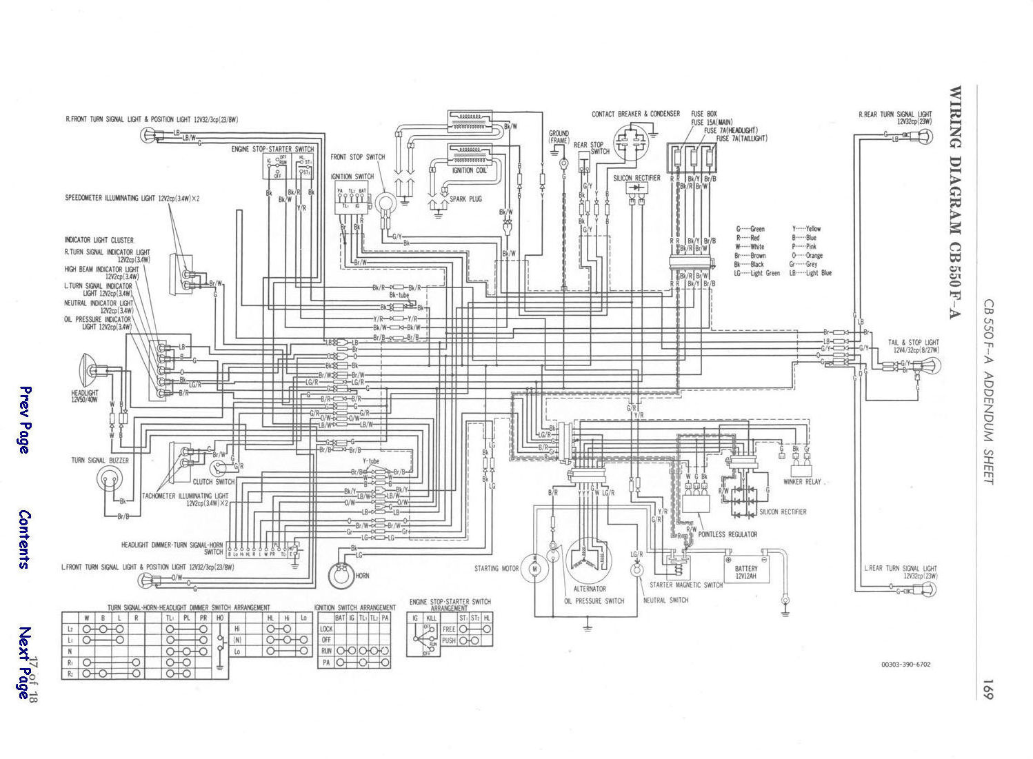
If you have any specific questions we can definitely help. For more general stuff, see trek's posted diagram. The colors should match up (more or less).
The two coil Blacks are switched +12vdc feeds controlled via the kill switch. "Black w white trace, on schematic" (With key switch on and Kill switch in run position +12vdc is fed to coils, in kill positions +12vdc is cut off to the coils = killing the engine). That way you can kill the engine via Kill OR Key switches.
As far as the M unit. I have no experience w that. Looks like it adds confusion to a pretty simple system.
As far as your drawing is concerned I question the two wires from the M unit "Start" terminals spliced together and feeding +12vdc to the starter solenoid??? Doesn't really seem right. As the start switch, bar controls has to be involved in the circuit somewhere.
And the key switch "accessories" appears as though it would be the "parking" position (brown & brown/white) on the key switch (feeding +12vdc power to tail, parking and gauge lights" only.
But like I said, I don't know M unit. Sorry I can't help more w that.
Also, no fuse for the wire heading from the battery to the solenoid. It pulls too much current to be fused. That connection should be direct to battery.
Thanks guys. Below is an updated diagram with a few changes.
- Black wire from each coil has been directed to the 'ignition' terminal on the m-unit blue.
- The starter solenoid goes straight to battery.
- Rectifier/Regulator goes straight to battery.
- The black wire on the rectifier/regulator goes to the 'ignition' terminal on my key switch.
Is this alright?
Also, will I need to add a relay to the key switch? If so how do i go about doing this?
No relay necessary on the ignition switch, but I would put a fuse on the red wire. 1A is good. Then move the black wire from the R/R over to the AUX port on the m-unit and off of the switch. The ignition switch should only go to the LOCK input.
This site uses cookies to help personalise content, tailor your experience and to keep you logged in if you register.
By continuing to use this site, you are consenting to our use of cookies.