Sparking/not sparking

sham

Been Around the Block
So, I think I "hot wired" my bike...


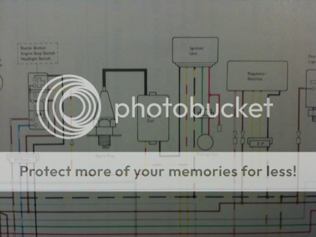
I was trying to test for a spark, and after matching up the various wires of the kit CDI, I hit the starter, but nothing happened. I switched around the wires connecting to the ignition coil (I understand it has a positive and negative?) and again, nothing. However, I noticed I was getting sparks by touching the wire which links directly to the ignition coil...but nothing happens when I hit the starter.


So, am I essentially just "hot wiring" the bike? I'm assuming there are some positives to take from this...


Thanks.
 
Oh I should add, from what I understand, the CDI doesn't work with electric advances - "This CDI module is not intended for use as a replacement for CDI units that generate their own high voltage from an inverter requiring a 12V battery supply."

The kz is an electric advance...so I'm just more curious how and why I was getting that spark - and I guess if it has any implications on whether the CDI could work or not.
 
What is that CDI expecting to use as a trigger and what does teh bike have as a trigger? I suspect that there's no pulse being transmitted to the CDI, but when you break the circuit, the capacitor discharges the same way it would do if it were triggered.
 
Ha that's a good question. I didn't think of asking that.


The instruction manual that comes with the kit states that the CDI can be used for an engine that "incorporates a generator and trigger coil to provide the high-voltage and the firing point."


The ignition system of the kz consists of a battery, a pick up coil, an IC ignition unit (CDI) and an ignition coil. Spark plug fires everytime the piston rises.


From how I understand it, the pick up coil is equivalent to the trigger coil mentioned.


The kz manual seems to suggest that the alternator controls the ignition timing by the advanced timing marks - is this the "generator" or is the ignition coil it?


Does this in anyway suggest that I should be able to use this CDI unit?
 
Not so far, but it hasn't ruled it out either.

What doesn't make any sense to me (because I don't understand this high tech stuff) is that they claim it can be triggered with any trigger - leading edge, trailing edge, square wave, other... Maybe it will.

Forget about the alternator and advance curve for a moment and let's see if you can get it to spark.

Is your trigger coil still in place and working? That would be a good place to start.

If you have an accurate meter you should be able to see at least a flicker as it pulses though you can probably not measure the output. Jaycar claims that teh unit can be used to replace a stock CDI, so what does the wiring diagram look like?

We'd expect to see one connection to the coil and one to the Trigger/pulse gerenator, plus ground and power leads. Is that how yours is wired?
 
Hmm I don't really understand the wiring diagram from the instructions to be honest. I'll try to put up an image later tonight. Would you know what exactly the generator coil is? Found another note saying the CDI is only compatible with engines with separate generator and trigger coils and which generates a positive high energy voltage to charge te capacitor bedew firing.

The last part Im understanding as referring to an electric advance, so I'm thinking the warning about it not working a a replacement for CDI units that generate their own high voltage from an inverter requiring a 12V battery doesn't apply to me - I imagine my unit has this separate generator coil and trigger coil they speak about, just not sure what the generator coil is lol, not that knowing will be the solution to my problems.

Shall try testing the trigger coil as you suggested. How do I get it to pulse but, and is it my pick up coil?
 
Actually I think I've wired it wrong. The generator coil is most likely the pik up coil, which creates pulse via some magnet. I assumed this was the trigger coil in my current set up.

However there are two wires running into the pick up coil, so I'll have tp work that out and what the generator coil is. It's definately not the ignition coil lol.
 
...I think I just did something bad.
I tried rewiring the CDI to what I thought would be the correct combination:
Generator coil to the alternator
Trigger coil to the pick up coil
Kill switch to kill switch
Chassis to chassis
Ignition coil to ignition coil...
I turned it on, the headlight went on, then died...

Now I don't get any response from the electronics.

Any ideas what went wrong?

I removed the terminals and put new ones in, cos I mangled them up so bad when I tried to get the wires out of the 6 plug connector. That's all I did tonight...
 
If you are lucky it just blew a fuse. If you are unlucky, the blue smoke escaped.

Check the fuse and then post the CDI wiring diagram and point me to a stock wiring diagram and I'll see if I can translate it.
 
It's a Kawasaki, I don't do them (every single one I've ever worked on has had electrical problems)
 
Thanks teazer, I'd appreciate that.

Here are the various diagrams. I've attached the schematic ignition diagram as well - the stock wiring diagram is in german from another ddt-er. I don't have access to a scanner at the moment and can't scan the one from the service manual. Actually I just had a comparison and its slightly different, so I've attached a close up phone pic of the CDI wiring instead.

[EDIT: You were right, blew a fuse on the white wire. Do I need an OEM fuse, or any fuse will do?]

Picture10-1.png

Picture11.png

10e970a4.jpg

8f241ede.jpg


Are other bike's much better in the electrical department? I'm thinking a kick start would have saved a lot of headache.
 
Actually, that red wire doesn't seem to be going to the alternator. I thought the box coming off that wire was it, but I found the alternator in the wiring diagram with its own wires (yellow)...
 
This is interesting - the blown fuse is a 15A fuse, but the service manual lists it as a 20A fuse...
Is this the problem?

Supercheapauto sells a pack of 5 20A fuse's for $5. Definitely getting some tomorrow. Hoping that the blown fuse means the CDI is working at least? The wire was going to/comes from (?) the starter relay.


6bad5c93.jpg
 
On any Japanese bike I've worked on, any time you see a Red wire, it's direct live to battery. (or, Red/White in your case)
It will ONLY go to ignition switch and rectifier
You could, as Teazer says, let the smoke out connecting it in the wrong place.
You may be lucky someone fitted wrong fuse, if they had fitted a 30A you would probably need another CDI
I'll take a look at diagrams
 
OK, The original looks like a DC TPI, not a CDI.
The coil is 'live' and 'grounds' through the box
With CDI the coil is grounded and gets a high voltage 'spike' when triggered (around 180~300V)
There is a possibility you fried the SCR (151?)
You need to transpose wire colours from Kawasaki to the 'box'
Black could be ground or live with ignition on, red, at least is 12v from ignition (so black is probably ground)
I'll have to open post up again so I can refer to diagrams easier
OK< second window open so I can switch ;D
You can use CDI but you are going to have to re-wire coil.
The R/Y from coil gets disconnected from main harness and connects to CDI coil terminal.
The black from coil gets connected to ground.
You already have the other connections?
You may not be able to use kill switch terminal (if it's 'live' you use kill switch harness wire as power IN to box instead of generator input, you don't have a 'charge coil'

That should work, as long as nothing is 'smoked'
 
Hey pj,

Thanks for going through that. I don't quiet understand everything you talke about but I'll try to decipher it when I have the bike in front of me. One question which I have now is whatdo you mean that I can use te CDI but have to rewire the coil? Are you referring to the CDI as the coil or are you referring to something else?

I'm assuming when you talk about te main harness, you're referring to the bunch of controls dealing with the starter button, engine stop switch and headlight switch. If that is true, then I was assuming the R/Y wire was the kill switch wire, but I'm understanding what you're saying as to wire that up to the box as the generator coil rather than kill switch wire and to keep the pick up coil wired to the box as the trigger coil?

I'll have a play when I get home.
 
In the schematic,(page N11?) #10 is Battery, #8 ignition switch
R/Y goes into coil and HAS to be positive side 12v (OK so far?)
CDI unit has a single wire coming out, you trigger CDI box and it sends 100+ volts to coil, other side of coil has to be grounded by something
You can't have 12V positive on one end and positive 100+ the other end without some sort of ground.
You have to have a complete circuit
Thinking about it, you probably need a CDI coil, it will have a lower internal resistance.
CDI means CAPACITOR DISCHARGE IGNITION, the capacitor has to discharge not complete a ground circuit

It would be a lot easier to get the correct TPI box, that way you have +12 one side of coil and when it grounds (through box) you get a spark, (N11 schematic, #5, is a TRANSISTOR, the T part of TPI)
you may be better off sending the aftermarket CDI back where you got it from
You can check coil by fitting a jumper to 'ground' side of coil and just 'flashing it to any good ground point on frame or engine, with 12v to one end,you should get a park as magnetic field collapses
 
Hey pj,

I'm going to try to rephrase what you said, and that is what I did.
Firstly, there are two types/sides of an electric flow - positive and grounded.
If one side of the wiring is connected to the ground (shown as a heavy line with hatching) the wire on the opposite side of the object is positive.

This is why you say the R/Y running from the Ignition switch has to the Ignition Unit (6) has to be positive.

From before I dismantled the 6 plug connector, I noted down the placement of each wire, which turned out to be useful as I found this illustration:

9eb9e0f6.jpg


From the illustration (and not the wiring diagram), that means:

2 Red/Yellow = Battery
Black = Ignition coil
Black/Yellow = Ground
Green = Pick up coil (-)
Red = Pick up coil (+)

If I transfer this back into N11,

2 Red/Yellow = Battery (+)
Black = Ignition coil (-) Because it is connected to R/Y which is already +
Black/Yellow = Ground (-)
Green = Pick up coil (-)
Red = Pick up coil (+)

Which means the circuit is incomplete, as there is one + missing. But this is necessary to actually get the spark, the capacitor has to discharge into the excess -, which is the Ignition coil, which in turn creates the spark (shown in N11 and in wiring diagram, where the spark plug is grounded and connected to the Ignition coil.

Translating this to the kit 'box' I made, I wired it as the following:

Generator coil = Pick up coil (+) R
Kill switch = Ignition coil (-) B
Chassis = Ground (-) B/Y
Trigger coil = Pick up coil (-) G
Ignition coil + = Battery (+) R/Y

I tried switching the Generator coil and Trigger coil around, but still nothing happened.

Is this a very dumbed down version of what you were saying? Lol.
Seeing as nothing happened apart from the usual whir of the alternator (?) I think I'll have to give up on this and buy an OEM ignition unit. Unless you can spot what I did wrong, perhaps its the transistor link which just doesn't work very well in this kit.
 
There are really a couple of problems.
First, as my original post, I don't 'do' Kawasaki's' not really comfortable with Kawasaki wiring colours when I don't have bike in front of me. (I worked pretty exclusive on Honda, Suzuki and Yamaha 95% of the time)
Secondly, you have a CDI unit when you need a TPI 'Ignitor' unit
I know I could make it work but trying to explain to someone over the internet is a little more than just difficult.
If it wasn't Kawasaki it would be easier as I wouldn't have to keep checking wiring colours

You really would be better off finding the correct ignitor unit rather han trying to make the wrong unit work.

You could search GM HEI electronic conversions and build a trigger unit for about $30.00.
There are plenty of instructions online for most manufacturers as many stock units fail.
I have a link for Kawasaki inline 4, just use 'one side' and single lead coil.
It has plenty of diagrams and pictures so should be real easy to make if you have a 20w soldering iron
http://home.comcast.net/~loudgpz/GPZweb/Ignition/GPZgmHEImod.html
There are simpler versions, Google for GM HEI conversions
 
It seems that a Kawasaki uses a pickup/trigger/pulse generator with 2 leads and both connect to the Ignitor whereas that CDI uses a single lead pulse generator. I'm sure that something could be made to work, but at least that GM HEI conversion uses a stock 2 lead pulser and is cheap reliable and known to work.

Nice link PJ - thanks for sharing.
 
Back
Top Bottom