Follow along with the video below to see how to install our site as a web app on your home screen.
Note: This feature currently requires accessing the site using the built-in Safari browser.
We noticed you are blocking ads. DO THE TON only works with community supporters. Most are active members of the site with small businesses. Please consider disabling your ad blocking tool and checking out the businesses that help keep our site up and free.
That looks like a lot of meat to be shaving off the head. Unless you run a custom thicker copper head gasket or something, I dunno if you'll have enough piston/valve clearance.
Gotta see the rest of the gasket surface. It looks bad but also possibly could be of no harm to the integrity of the gasket surface. There's a lot of heads and jugs out there like that. It could be assembled improperly and not seated.
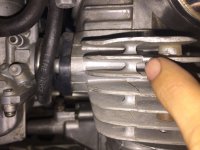
there is that dang hidden screw :
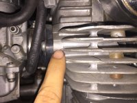
but actually you do use a pry bar ,heal bar, tire iron ,a crow could work fine ,big screwdriver as a wedge...the key is finding the cast in wedge or pry points, factory fulcrums. most jap stuff has them it still may require fin wedges to spread the force up the stack
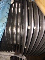
Those ridges are part of the casting process. Each fin is actually it's own layer of the mold, they're all stacked onto one-another to form the final solid piece. That's why you will see lines corresponding with each fin going all around the head, such as on CB350's.
The large rounded ridges are actually just oil passages. I know you know that but there are others watching us, yano?
Buuuuut you get 100% of the points in this thread because that's exactly the...."flaw?" in the SOHC's. Damn 6mm head bolts on each side hang a lot of folks up.
As a hint, you can tell if it's the gasket or bolt that is holding the head together. The gasket would have at least SOME give. If it's a bolt, it will be SOLID as steel!
Yes the ridges are part of the casting process, but the pad that XB points out is placed right by em for a reason. it's because that's where you pry, if you are unresourcefull enough to need to pry on a head at the gasket surface.
Obviously. Honda was probably ahead of the other Jap brands in ensuring their service monkeys could get the job done without turning into a winging brit. I sometimes feel like England's problems are all England's fault. It's a vicious circle, but fun on the outside looking in.
i can usually just smak a head dead straight to the fins on each side with a rubber mallet the shock can crack the seal and then they will lift off.but the hit it better be straight on .they snap off easy you dont need to ask me how i know : :-X :-[ :-[
other times they dont need any fear put into them they lift off clean and easy,lots of them need a gentle to a stout pry
now base gaskets those seem to allays get stuck more worser in my experience ,some are scary stuck hard theres usually pry pads down there as well
but yeah the hidden bolt the japs love that , i swear its revenge for the a bombs
that fooked up area it would be a good place to use slow set jb weld
drill a few shallow 3/32 holes to act as anchors for the epoxy give the patch legs,cant slide out, dress it down then surface scrub it a thin dab of 518 for good measure on final
Those ridges are part of the casting process. Each fin is actually it's own layer of the mold, they're all stacked onto one-another to form the final solid piece. That's why you will see lines corresponding with each fin going all around the head, such as on CB350's.
This isn't an accurate description of the process. The seams in the molds are the little raised lines running perpendicular to the fins at the corners of the heads. There is also a mold seam at the pry point. If you look closely to the corner of the head, you can see where one fin is higher on one side of the seam than the other because the mold didn't perfectly line up. In lost wax casting, a mold is a solid unit cast over the wax positive. However, the process requires each unit be an individual mold. In order to produce the wax positive, you need a reusable mold. That's where those seam lines come from.
i can usually just smak a head dead straight to the fins on each side with a rubber mallet the shock can crack the seal and then they will lift off.but the hit it better be straight on .they snap off easy you dont need to ask me how i know : :-X :-[ :-[
Dev, the master molds are made by hand. How could you achieve the voids and blind holes in some areas without stacking small slices of the piece one layer at a time?
Yes, as for the molds which are used for casting, they have their own seems from assembling them, but they carry on the lines from the hand-made master piece.
The first picture shows where the production casting mold parts. This entire rear section of the head is made from one piece of a mold, one of many that are clamped together to form one solid casting negative.
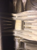
The second is where the original master was assembled by stacking one slice at a time to create voids which would otherwise have been impossible for casting a master negative.
Last is a void which would be impractical to make into a mold if not for having stacked many slices of the piece to form the one solid piece.
Dev, the master molds are made by hand. How could you achieve the voids and blind holes in some areas without stacking small slices of the piece one layer at a time?
Lost wax or foam. You make a master out of wax or foam. A master mold can have many, many parts. Something as simple as a symmetrical ball will have two parts, where more complex forms will have many. A simple Coke bottle is made of up 3 parts- two for the sides and the third for the bottom. I've made molds with over 30 individual parts. Every one of those thin raised lines was a seam between parts of the mold. With a ceramic-shell mold, you coat the wax positive in a ceramic shell slurry, with a pour spout and channels of sprigs going all over the place for air. Put the mold in a kiln upside down with the spout down and melt the wax out. Your cast will fill the empty cavities left when the wax melts out. In sand casting, you're producing a positive out of foam from a mold that's nearly identical to the mold for wax. However, for the metal form you build the sand mold in layers. The sand is a mixture of silica sand and bentonite so that it holds its form. Sand alone would collapse on itself. When the metal is poured into the sand mold, it vaporized the foam and replaces it in the voids.
The second is where the original master was assembled by stacking one slice at a time to create voids which would otherwise have been impossible for casting a master negative.
Last is a void which would be impractical to make into a mold if not for having stacked many slices of the piece to form the one solid piece.
That seam your finger is pointing to in the first pic is where that entire side was attached to the middle section. That seam is the bottom of the side section as poured into a one-part mold or a stacked mold (like ceramic tiles). You're right in that the wax master was assembled, but you're wrong as to how.
They stack all of the pieces which are delineated above at the seem of the heat veins. Then assemble those sub parts (that one rear-piece, for example) onto other sub parts, and that forms one positive which is then used to make a negative that is then filled with aluminum. Right?
This site uses cookies to help personalise content, tailor your experience and to keep you logged in if you register.
By continuing to use this site, you are consenting to our use of cookies.


")