wiring new DCC switches to 1969 cb350

david.boettcher

New Member
guys-

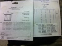
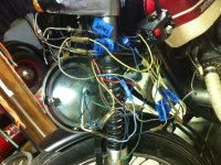
im slowly turning my stock 1969 cb 350 into a more modern tracker/brat and have replaced the original handlebars with new bars and new switches from dime city cycles. i purchased one of their left side turn signal/light/horn switches and right side start/kill switches. Im having trouble with wiring these to my wiring harness and am stuck on whats wrong. Currently, the left side headlight switch all works (hi/low beam, horn, brake) when i have the key turned to accessory. when i turn the key to the start position nothing works except the brake light is half lit. As for the right side start switch, nothing works. Ive attached a few pics, maybe theyll help someone point out what im doing wrong. Im following a wiring chart i downloaded for the ko cb 350 and have the wire chart for the switches but just dont understand what ties to what,..

side note- i have no clue what im doing with wiring. please excuse my sloppy connections/use of random wires to make things work.
 

Attachments

  • wiring chart.JPG
    wiring chart.JPG
    489.5 KB · Views: 244
  • wiring mess.JPG
    wiring mess.JPG
    596.5 KB · Views: 286
The only thing I can think of is that maybe your switches have to ground to the bars, a lot of them do
 
SONICJK said:
The only thing I can think of is that maybe your switches have to ground to the bars, a lot of them do

i was wondering that myself. you might be able to see in the pic of the wiring, the light switch has a metal jacket on the inside that clamps around the bars... i was wondering if i had to sand the paint off the bars to ground this clamp to it. ever done anything like that?
 
Yes thats exactly how its done.
For the moment to test, grab some wire and wire it to the ground on the switch and then to a good ground on your frame and see what happens
 
I hope you get it figured out and post the solution. I'm considering their switches myself. Do they seem like sturdy well made units?

I like how they put this warning on the bottom:
wiringchartJPG_thumb_zpsa0c0eecd.jpg


John
 
SONICJK said:
Yes thats exactly how its done.
For the moment to test, grab some wire and wire it to the ground on the switch and then to a good ground on your frame and see what happens

will give it a shot tonight. thanks sonicj
another question, I have a solid yellow wire and a solid white wire that ive think is from the alternator. ive wired them together as ive read thats the thing to do. they have constant power even when the bikes off. am i messing something up there? you can see them in my pic as well
 
sourjon said:
I hope you get it figured out and post the solution. I'm considering their switches myself. Do they seem like sturdy well made units?

I like how they put this warning on the bottom:
wiringchartJPG_thumb_zpsa0c0eecd.jpg


John

ya, that little warning is just great!
the switches are good. theyre sturdy, the finish isnt perfect but they seem like theyll work well... if you can figure out how to wire them up!
 
I'm curious if this is going to work. I installed the same kit on mine, but i rebuilt my harness from scratch. (it sounded like fun at the time) all of my components are grounded on one end and the switch is placed before the device in the circuit (i.e. Hot -> handlebar switches -> device (horn, light, t/s etc) -> ground

One thing i found strange, well... just different i guess, is the headlights on the LT controls have a H for headlights, P for parking lights, and * for .. something else i guess. on my setup it's the same as H. Not sure what this dot is supposed to be.

Looking at the stock wiring though, they have the headlights grounding through the switch, so in that scenario, you'd wire red to ground, and your hot would be wired to the light, and then the h and l beams wired to the corresponding green and yellow on the switch.

One more note, if memory serves, there's only 2 grounds on that switch, horn and kill and they're wired independent of all other components. so this device doesn't actually have a common ground wire.

get a continuity tester and you'll see what i mean.
 
I'm looking at getting a similar sort of set up, if I come across any issues similar to this I guess you're my man!
 
How's this coming? I'm about to install some new controls on my cl350. I'd be very interested in your final product.
 
Back
Top Bottom