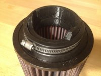
but that bellmouth is actually only at its efficiency when in open air or well inside a large box
clamping a filter to it negates much of its effect and intended efficiency
it is designed to let air spill in smoothly from all around it ,hence its form with the scuplted round as apposed to a thin sharp bellmouth that you see on lots of stacks
clamping a filter to it negates much of its effect and intended efficiency
it is designed to let air spill in smoothly from all around it ,hence its form with the scuplted round as apposed to a thin sharp bellmouth that you see on lots of stacks
")