'81 TR1 build.................(yup another Mojave tank combo!!)

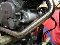
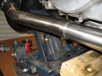
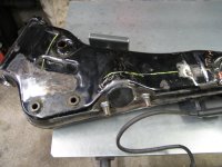
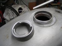
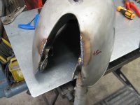
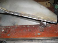
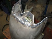
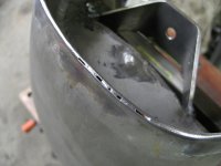
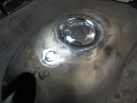
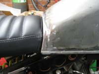
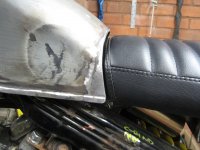
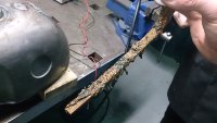
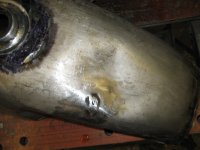
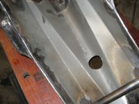
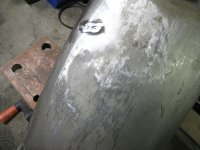
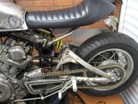
got the exhaust all welded up. purged it during the welding phase so its nice and smooth internally, bit tricky on some of the tight stuff, but managed to do most of it without too many holes appearing !!!

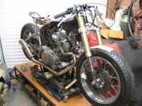
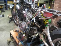
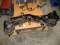
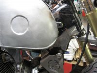
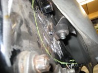
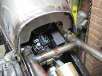
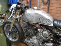
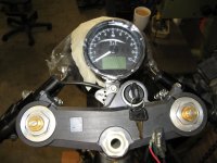
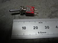
Next job was to temporarily rig up the wiring to see if it would spark up..........???

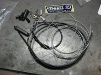
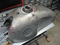
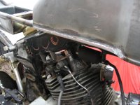
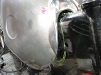
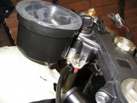
when that was finished I got all excited and made up the throttle cable out of a 2-1 kit from venhill. Mounted the carbs, and filled up the float bowls with some fresh unleaded and crossed my fingers.................

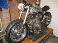
got the coils mixed up during the initial attempt, resulting in a nice back fire out the carbs next to my ear

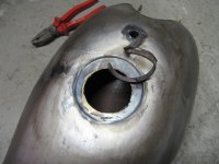
flattened the bike battery before I noticed it, but then jumped it off the car battery and away she went :D:D:D:D

obligatory "she's alive" video attached

https://www.youtube.com/watch?v=3ltlqDkuLXU
 

Attachments

  • IMG_3650.JPG
    IMG_3650.JPG
    2.8 MB · Views: 308
  • IMG_3655.JPG
    IMG_3655.JPG
    2.7 MB · Views: 282
  • IMG_3661.JPG
    IMG_3661.JPG
    2.7 MB · Views: 332
  • IMG_3662.JPG
    IMG_3662.JPG
    735.3 KB · Views: 293
  • IMG_3664.JPG
    IMG_3664.JPG
    2.5 MB · Views: 307
too right..........adds to the "will she, wont she" turn over excitement ;D ;D ;

reminds me of my Ducati dry clutch at idle ;D
 
managed to get a few hours on the bike over the Xmas break, not enough though !!!

De-tabbed the main frame, and cut off some of the bits I didn't need. Blanked off the air intakes into the frame and used the space to mount the coils which normally sit out front above the cylinder head.

Made a little platform to locate the new spark generator box of tricks, plus mounted the new rectifier. Positioned it so it should get plenty of airflow through the forks just under the front of the tank.

Knocked up a couple of lock-stops and tacked them in place to line up with the GSXR fork clamp.
 

Attachments

  • IMG_3691.JPG
    IMG_3691.JPG
    2.4 MB · Views: 274
  • IMG_3687.JPG
    IMG_3687.JPG
    2.7 MB · Views: 285
  • IMG_3686.JPG
    IMG_3686.JPG
    2.7 MB · Views: 281
  • IMG_3681.JPG
    IMG_3681.JPG
    2.6 MB · Views: 267
  • IMG_3676.JPG
    IMG_3676.JPG
    2.5 MB · Views: 263
turned my attention to the tank..........

I knew before I bought it that they could be a bit rough !!! This one didn't let me down.................

Much as i admire the skills of the Indians to put one together............better than I could achieve anyhow, it still needs a fair bit of work.

First job was to get some brackets on it to secure it to the front of the frame. Its sitting on the original rubber mounts but i wanted a bit of extra security to stop it coming loose??

Then onto the "missing" bits :D............its not very symmetrical when you look at it from certain angles, so i set about filling in some of the errors with the mig. Bit more work required with grinding back but should come out ok?

The tanks have a reputation for leaking........ and I can already see some pinholes in this................ before I get near any fuel I'll be pressure testing and repairing as needed.

The filler I was never happy with as it looks like its been made from an old exhaust pipe, with some weird pitch thread and it was brazed in, off center???? so that came off ready for my 1/4 turn neck to go in.

Still lots to do on it.....
 

Attachments

  • IMG_3718.JPG
    IMG_3718.JPG
    2.6 MB · Views: 271
  • IMG_3714.JPG
    IMG_3714.JPG
    2.8 MB · Views: 272
  • IMG_3706.JPG
    IMG_3706.JPG
    2.5 MB · Views: 290
  • IMG_3696.JPG
    IMG_3696.JPG
    519.3 KB · Views: 278
  • IMG_3698.JPG
    IMG_3698.JPG
    2.6 MB · Views: 286
Decided to ditch the mounting tags on the tank so they are now in the in the recycling bin.............

Used a couple of rubber bungs I had lying around, then make up some brackets to weld onto the tank/frame. Much happier with the look and the tank is more secure.

Also cut out the brazed in filler neck base, ready for the new 1/4 turn spigot to go in......................talking about the tank........as I had it on the bench i decided to pressure test it....

I had read before I bought one that they can be a bit suspect. This one did not disappoint............The seams needed a lot of tidying so i decided to see how much meat was on them with the die grinder, soon found my answer...........NOT A LOT !!!

Started off filling in the blanks with the tig, but was going through filler at alarming rate of knots, swapped over to the mig to fill in the rest missing bits. Still a lot of work to do on it...
 

Attachments

  • IMG_3751.JPG
    IMG_3751.JPG
    581.1 KB · Views: 268
  • IMG_3749.JPG
    IMG_3749.JPG
    2.8 MB · Views: 271
  • IMG_3742.JPG
    IMG_3742.JPG
    2.4 MB · Views: 269
  • IMG_3759.JPG
    IMG_3759.JPG
    2.2 MB · Views: 274
  • IMG_3758.JPG
    IMG_3758.JPG
    2.6 MB · Views: 283
  • IMG_3726.JPG
    IMG_3726.JPG
    2.3 MB · Views: 261
  • IMG_3725.JPG
    IMG_3725.JPG
    2.5 MB · Views: 268
  • IMG_3722.JPG
    IMG_3722.JPG
    3.7 MB · Views: 273
  • IMG_3720.JPG
    IMG_3720.JPG
    2.8 MB · Views: 250
lots more work on the tank............

found a few more leaks in it after filling with water so ended up grinding yet more of the original seams back and re-welding them, grinding back, re shaping etc, etc.

also added in a few extra bits and pieces to make the seat mating area a bit neater, plus added in a filler around the tunnel, welded in the new 1/4 turn neck.

even though its taken hours and hours, just to get to this, it still beats making one from scratch??? Few more little bits to do and its finished ready for some filler....
 

Attachments

  • IMG_3807.JPG
    IMG_3807.JPG
    2.3 MB · Views: 272
  • IMG_3806.JPG
    IMG_3806.JPG
    2.5 MB · Views: 282
  • IMG_3796.JPG
    IMG_3796.JPG
    2.6 MB · Views: 278
  • IMG_3791.JPG
    IMG_3791.JPG
    2.7 MB · Views: 264
  • IMG_3786.JPG
    IMG_3786.JPG
    2.4 MB · Views: 267
  • IMG_3783.JPG
    IMG_3783.JPG
    2.3 MB · Views: 274
  • IMG_3779.JPG
    IMG_3779.JPG
    2.5 MB · Views: 250
  • IMG_3775.JPG
    IMG_3775.JPG
    2.6 MB · Views: 267
  • IMG_3767.JPG
    IMG_3767.JPG
    2.4 MB · Views: 258
  • IMG_3761.JPG
    IMG_3761.JPG
    2.7 MB · Views: 272
before i put any petrol in it I decided to remove some of the rust I could see inside. this was the result after 12hrs electrolysis hooked up to a 6v power supply................not bad for a new tank :eek:
 

Attachments

  • DSC_2352.JPG
    DSC_2352.JPG
    1.8 MB · Views: 291
  • DSC_2354.JPG
    DSC_2354.JPG
    1.7 MB · Views: 274
Great work so far, especially on a bike in need of a little attention... Impressive fabrication
 
few more hours spent on the tank.........nearly ditched it at one point!!!! last Mojave tank project for me :eek:

after de-rusting the tank I decided to give it one last leak-test over a few days. Man what a pain in the butt!!! Took the decsion to grind back all the seams I'd not been near so I could rest knowing it was not going to leak....................

also made a balance pipe to fit between the tank halves as the tunnel is so deep on it, this should allow the petrol to balance out as it gets gobbled up by the 1000cc V-twin
 

Attachments

  • IMG_3826.JPG
    IMG_3826.JPG
    2.7 MB · Views: 262
  • IMG_3825.JPG
    IMG_3825.JPG
    615.7 KB · Views: 274
  • IMG_3822.JPG
    IMG_3822.JPG
    3 MB · Views: 284
  • IMG_3834.JPG
    IMG_3834.JPG
    2.6 MB · Views: 269
unfortunately during the filling, checking, emptying, filling process I managed to drop the tank off the bench full of water. luckily it hit my shin on the way to the ground, but still made a that dull thud of denting metal noise when it eventually impacted the concrete !!!

After i'd stopped hopping around i turned the tank over and surveyed the damage !!!

Decided to go in through the back (OOO-err missus) and knock as much out with a piece of wood. Its looking a bit battle scared but managed to get most of it knocked back out.
 

Attachments

  • IMG_3829.JPG
    IMG_3829.JPG
    2.6 MB · Views: 278
  • IMG_3828.JPG
    IMG_3828.JPG
    2.3 MB · Views: 269
  • IMG_3831.JPG
    IMG_3831.JPG
    3 MB · Views: 252
had enough of metal bashing, which is all I've been doing for the last few weekends so got on with some of the mechanicals....

turned my attention to the rear sprocket alignment and fixing. Its a triumph rear wheel which does not quite line up with the front sprocket. The sprocket bolts were a bit too close to the swing arm, so I had to remove them from the hub by welding the old nuts on as they were loctited in place.

I decided to make up some new studs from some 12.9 bolts I had, this would give me the clearance i needed. I used some flanged nuts which I castellated as the standard nuts would not pass. Drilled the studs ready to lock-wire in place on assembly.
 

Attachments

  • IMG_3862.JPG
    IMG_3862.JPG
    2.8 MB · Views: 255
  • IMG_3856.JPG
    IMG_3856.JPG
    2.8 MB · Views: 259
  • IMG_3836.JPG
    IMG_3836.JPG
    2.6 MB · Views: 244
  • IMG_3818.JPG
    IMG_3818.JPG
    2.7 MB · Views: 240
  • IMG_3533.JPG
    IMG_3533.JPG
    763.2 KB · Views: 259
  • IMG_3443.JPG
    IMG_3443.JPG
    2.3 MB · Views: 256
  • IMG_3404.JPG
    IMG_3404.JPG
    2.7 MB · Views: 270
had to make a spacer for the front sprocket. There was no shoulder on the shaft for a plain spacer so had to file a splined version to get the aliment right.
 

Attachments

  • IMG_3876.JPG
    IMG_3876.JPG
    692.6 KB · Views: 240
  • IMG_3875.JPG
    IMG_3875.JPG
    2.8 MB · Views: 248
  • IMG_3874.JPG
    IMG_3874.JPG
    602.6 KB · Views: 229
  • IMG_3853.JPG
    IMG_3853.JPG
    2.8 MB · Views: 239
front brake calipers next...........

machined my over-sized spacer brackets for the pad alignment, then turned my attention to the left side caliper. The VFR800 Honda which they came off has an antilock braking system fitted as standard. This I discovered means the middle piston is controlled by the rear brake. I read all sorts of wonderful extra brake pipe solutions to link all 3 pistons together, but decided to take a simpler approach. Just took it apart and drilled it internally to link all three. just need to make a blanking plug for the extra central brake pipe hole and job done....
 

Attachments

  • IMG_3870.JPG
    IMG_3870.JPG
    2.7 MB · Views: 268
  • IMG_3869.JPG
    IMG_3869.JPG
    752.7 KB · Views: 246
  • IMG_3849.JPG
    IMG_3849.JPG
    2.6 MB · Views: 253
  • IMG_3847.JPG
    IMG_3847.JPG
    2.7 MB · Views: 256
  • IMG_3871.JPG
    IMG_3871.JPG
    2.7 MB · Views: 259
  • font left.jpg
    font left.jpg
    114.6 KB · Views: 247
had some nice bits turn up in the post over the last few weeks so decided to get them on.

some nicely machined clip-ons from our friends in the far east.............

and a nice speedo/rev counter from Germany.

threw some of the other bits on just for a bit of a morale boost...................sometimes I think you need to get some bits on there to get a vision of the end goal.....working with boxes of parts and fabricating bits and brackets sometimes gets a bit tedious ::)
 

Attachments

  • IMG_3908.JPG
    IMG_3908.JPG
    2.8 MB · Views: 264
  • IMG_3907.JPG
    IMG_3907.JPG
    718 KB · Views: 241
  • IMG_3905.JPG
    IMG_3905.JPG
    2.6 MB · Views: 296
  • IMG_3902.JPG
    IMG_3902.JPG
    2.8 MB · Views: 263
  • IMG_3892.JPG
    IMG_3892.JPG
    1.8 MB · Views: 247
  • IMG_3891.JPG
    IMG_3891.JPG
    2.6 MB · Views: 255
  • IMG_3884.JPG
    IMG_3884.JPG
    2.5 MB · Views: 246
spent the past hour going over all 5 pages...

wow, otherwise speechless.
 
been messing around this weekend with the switch gear. decided to go all stealth like and keep it simple. will be using some small push-buttons for the horn and main beam, then a small toggle switch for the lights. They'll be wired through some relays, so hopefully they'll be man enough to do the job.....
Can feel them quite nicely through a gloved hand, and easily reachable..
 

Attachments

  • IMG_3966.JPG
    IMG_3966.JPG
    598.4 KB · Views: 221
  • IMG_3964.JPG
    IMG_3964.JPG
    2.6 MB · Views: 205
  • IMG_3959.JPG
    IMG_3959.JPG
    578.7 KB · Views: 218
  • IMG_3957.JPG
    IMG_3957.JPG
    2.7 MB · Views: 225
  • IMG_3952.JPG
    IMG_3952.JPG
    2.9 MB · Views: 218
  • IMG_3950.JPG
    IMG_3950.JPG
    2.2 MB · Views: 229
  • IMG_3945.JPG
    IMG_3945.JPG
    2.5 MB · Views: 206
  • IMG_3941.JPG
    IMG_3941.JPG
    2.9 MB · Views: 223
  • IMG_3928.JPG
    IMG_3928.JPG
    2.6 MB · Views: 242
  • IMG_3914.JPG
    IMG_3914.JPG
    2.7 MB · Views: 236
  • IMG_3948.JPG
    IMG_3948.JPG
    2.2 MB · Views: 211
lchris21 said:
next job was to get the seat mounted..........out with the tube benders and welder.

machined a few fixing points and brackets...........

quick side on view to see if it looked right??
Awesome build!!
Do you recall where you got those weld-in mounting points for the rear subframe?
 
Back
Top Bottom