Follow along with the video below to see how to install our site as a web app on your home screen.
Note: This feature currently requires accessing the site using the built-in Safari browser.
We noticed you are blocking ads. DO THE TON only works with community supporters. Most are active members of the site with small businesses. Please consider disabling your ad blocking tool and checking out the businesses that help keep our site up and free.
thanks, just wish I had as much access to the CNC stuff I find on your great build......... 8)
saying that, I'm not too badly kitted out, just gotta use what you've got eh!!!
thanks, just wish I had as much access to the CNC stuff I find on your great build......... 8)
saying that, I'm not too badly kitted out, just gotta use what you've got eh!!!
Thanks man! Unfortunately I left my machinist job to teach welding full time at the local JVS, and no longer have all the CNC equipment available that I did =/ I have always said I make up for my lack of skill with CNC equipment. Good news is I may end up teaching some of the new machining program here at the school next year, and who is to say some of my "demonstration parts" may not just happen to fit a 1974 CB550..... Looks like you do very well with what you have to say the least. Craftsmanship may not always show to everybody, but it shows to fellow craftsmen.
It don't rain here in Wales................ ;D Just down the road butt, in Neath.
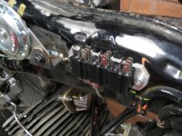
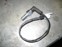
This puppy will not be seeing much rain when its on the road. They're only controlling horn/main beam so no biggie if I get caught in a shower, just dazzle the oncoming drivers and nice blast of the horn to go with it !!!
Know Neath a bit, worked in 3M Motorycles Swansea for a couple of years (before Mount Motors took them over and laid me off Dec 23rd 1990)
Delivered a few bikes there.
Worked for UK Plant when the roads were being dug up for fiber optic cables as well.
The good old days ;D
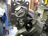
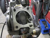
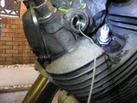
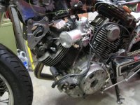
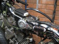
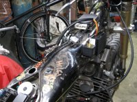
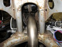
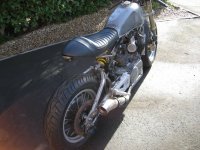
Also finally found a location for the oil pressure switch mod I planned. This took a lot of head scratching to find the best place.
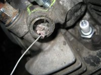
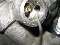
As we know full well, this engine was designed with an oil level sensor only, and had no provision for a switch. there's a few threads on the web about running extra pipework, drilling the oil filter housing, shoving in small gauges here and there, but I decided to try and keep it neat and simple. Found a small oil gallery on the front head cam feed, picked up a small pressure switch online (think it was an old British Leyland spec) rated to 0.8bar, so plenty of warning if I start losing pressure. Drilled the head in place with some strategically placed bungs to prevent the swarf getting in where it shouldn't.
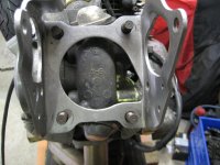
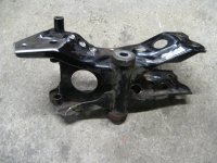
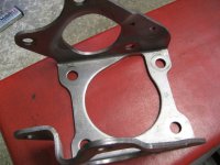
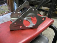
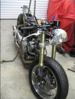
Same time I took some meat off the bulky brackets supporting the engine and rear sub frame...
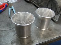
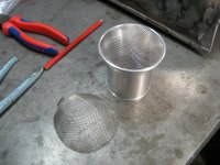
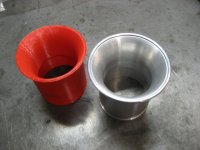
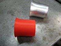
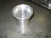
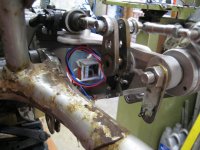
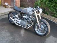
looked all over the web for some velocity stacks for my Minkuni carbs, but they were like rocking horse poo....or really expensive. So started messing round on the cad, modelled one up, and printed out a plastic test piece. When it looked right I got a local CNC shop to make a pair for me. I could have done it manually but would have taken 10 times longer and I hate machining aluminium with all that stringy swarf !!
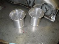
Got hold of some stainless mesh to complete the job....
These ain't been flow tested on a bench or anything, so are purely pose value at the local cafe :
I've got some proper filters from weekend blasts.....
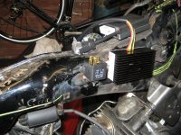
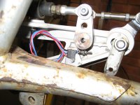
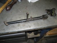
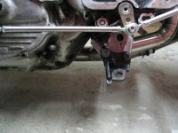
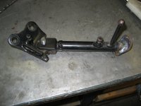
the rear brake pressure switch I was going to use was not playing ball when fitted to the master cylinder, it was a bit too close to the swing arm, so I had to get hold of a small sealed micro-switch and mount it down on one of the pedal linkages...
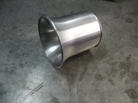
groove machined at the tip. the dish in the mesh keeps it in tension. I'll probably add a few drops of adhesive in there when the time comes just to make sure they don't rattle loose....
This site uses cookies to help personalise content, tailor your experience and to keep you logged in if you register.
By continuing to use this site, you are consenting to our use of cookies.

")