We noticed you are blocking ads. DO THE TON only works with community supporters. Most are active members of the site with small businesses. Please consider disabling your ad blocking tool and checking out the businesses that help keep our site up and free.
You are using an out of date browser. It may not display this or other websites correctly.
You should upgrade or use an alternative browser.
You should upgrade or use an alternative browser.
1974 CB360 "Pickled"
- Thread starter Luck
- Start date
crazypj
Split personality, I fake being smart
0.003" exhaust, 0.002" intake. I never use metric on screw adjuster bikes. Got sets from Harbor Freight and checked them, they are accurate on small sizes (didn't check the larger ones) Walmart has feeler gauge sets and they are accurate as well
Make sure your on compression stroke and not overlap, since you had cam cover off you know you have to turn motor over to do 'other side'
Make sure your on compression stroke and not overlap, since you had cam cover off you know you have to turn motor over to do 'other side'
Luck
Been Around the Block
.009. I was just checking things out with the timing and such and came to find ou that I cant seem to get the motor turned over. as I push on the kickstart it stops dead. The front valves have no room for movement. Im not coming up with a reason other than maybe the cam sprocket being in the wrong way? I believe I put it in when the LT was lined up on the rotor. Oh man! 2 steps forward, three steps back. Keep plugging away I guess.
Luck
Been Around the Block
Luck
Been Around the Block
Thanks Xb33bsa for the feedback. After pulling off the head yet again, Im trying to make sure I have all my bases covered before I have to clean the threadbond off for the fourth time.  I was just checking my cam chain tensioners. Took off the rear tension holder and began loosening up the adjuster. Nothing happened so I loosened some more. Loosened a third time and ziinnngg, the rear tensioner shot across the garage. I'm guessing it had been stuck in the same position for the past 40 years. It was quite easy to reinstall the tensioner holder before but now that it's free i can hardly push it down to start the screws. Are they always this difficult when working correctly or did I really loosen something up?
I was just checking my cam chain tensioners. Took off the rear tension holder and began loosening up the adjuster. Nothing happened so I loosened some more. Loosened a third time and ziinnngg, the rear tensioner shot across the garage. I'm guessing it had been stuck in the same position for the past 40 years. It was quite easy to reinstall the tensioner holder before but now that it's free i can hardly push it down to start the screws. Are they always this difficult when working correctly or did I really loosen something up?Tensioner has 2 springs. and YES they are stiff. You can use a looong screwdriver to reach down into the tesioner cup and push it down, OR make the "special tool".
Be careful the bottom end of the tensioner IS installed inside the cup correctly. If you look at the " tensioner update" it shows 2 examples how easy it is to miss the cup entirely and install the tensioner outside the cup but will still "appear" to be correct. This would be F-ed up. and destroy something.
AND dont lose the little seat thing that fits inside upper cup. when you turn it upside down to fit it over the end of the tensioner slide, it can drop out and fall into the bottom of engine.
Luck
Been Around the Block
Would a person be able to feel the difference in spring pressure when tightening or loosening the tensioner bolt? I have backed it out and cranked it in and I don't see much of a difference on the cam chain. Also what is the actual purpose of the 3mm threaded rod trick? I better do dome more reaserch.
Luck said:Would a person be able to feel the difference in spring pressure when tightening or loosening the tensioner bolt? I have backed it out and cranked it in and I don't see much of a difference on the cam chain. Also what is the actual purpose of the 3mm threaded rod trick? I better do dome more reaserch.
No, the bolt is simply a locking bolt. It just jams the spring loaded rod.
I think the tool is used to pull the tensioner arm down ? ? I cant see any reason to push it up...the springs do a pretty good job of that.
Like I said, easier to use a long screwdriver to reach down inside and push arm down. Then lock down bolt to hold it in place while you install slide. once installed loosen bolt.
+1. The key is understanding how the "adjuster" works. Like Trek said, it is a lock, not really an adjuster. Once the engine is assembled, you rotate the crank to pull all the slack out of the non adjuster side of the cam chain. This of course puts all the slack into the idjuster side. The idea is that the spring (s) in the adjuster mechanism will place the correct tension in the slack side, so all you do is loosen the lock, allow the springs to apply the correct pressure, and then re-apply the lock. When the engine is running, the springs and adjuster don't do anything. All the parts are fixed, and simply guide the chain. Eventually the chain gets a bit longer through stretching and wear, and you just repeat the procedure to restore a slack-free path for the chain.
Luck
Been Around the Block
Perfect. Thank you guys. I was under the impression it tightened or loosened the cam chain. I also thought the 3mm bolt or rod tool was used to reach the tensioner once it had gone to far. To clarify, what has been stated. The adjuster simply holds the chain in its position. If I use the 3mm tool, push the rear tensioner down and bolt in the holder or use a long screwdriver, they are all going to get me to the same place.
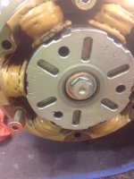
I have managed to get things worked out with that and now I'm working on the Tappets. Per the instructions, I bring the rotor to the LT mark. Do the left side, 180* counter clockwise to the T and I do the right side. As I have been playing with it, the Lt isn't 100% inline with the mark. I have to hold it there to get it lined up perfectly. I tried to check and see if both valves are closed and they seem to be. Should I do the Tappets with it exactly on LT or 1/8 to 1/16th inch off? I did it the way it was. Correct? I then tried to turn it to T but it turns quite a ways past. Should I hold the T next to the mark and do the Tappets for the right side? Get ready for questions about the points next. ???
I have managed to get things worked out with that and now I'm working on the Tappets. Per the instructions, I bring the rotor to the LT mark. Do the left side, 180* counter clockwise to the T and I do the right side. As I have been playing with it, the Lt isn't 100% inline with the mark. I have to hold it there to get it lined up perfectly. I tried to check and see if both valves are closed and they seem to be. Should I do the Tappets with it exactly on LT or 1/8 to 1/16th inch off? I did it the way it was. Correct? I then tried to turn it to T but it turns quite a ways past. Should I hold the T next to the mark and do the Tappets for the right side? Get ready for questions about the points next.
???Attachments
crazypj
Split personality, I fake being smart
If you have to hold crank in correct position you probably have things lined up right.
The valve springs are trying to 'push' the rockers back up and, because of chain, turn crank.
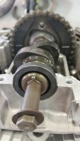
The pic you posted of cam with lobes up is the overlap position, you adjust valves with lobes down in compression position (positions are relative to rocker arms pressing on cam and valve tip)
The valve springs are trying to 'push' the rockers back up and, because of chain, turn crank.
The pic you posted of cam with lobes up is the overlap position, you adjust valves with lobes down in compression position (positions are relative to rocker arms pressing on cam and valve tip)
Another good example of something made a lot easier and less stressful by understanding a bit of basics. Adjusting the valves in concept is pretty simple. The precise location of the crank is not really critical. The idea is to rotate the lobe of the valve you are working on to be in a position where it allows the widest gap in the valve train, or in other words is as loose as it ever gets. Commonly this is convenient at top center on the compression stroke because both intake and exhaust valves are completely closed and you can check them both at the same time. In your case, you can verify that you have the cam in the right place just looking it it with the cover off and noting the rocker is on the heel, or base circle, or lowest part of the cam lobe. It does not actually have to be 180 degrees opposite of the high part of the lobe - most of the cam profile is the base circle, so technically you can use any of it.
The crank often does not like to stay put is any exact spot because forces from the valve train on other cylinders applies some rotational force, and/or the permanent magnets in the generator try to push it around. Don't worry too much about it. Look at the rockers on the valves you are working on while moving the crank back and forth at the marks.
You will see the crank moves, but it is not affecting the valves you are working on at its current position.
Keep in mind that valve lash is a bit counter intuitive. Too loose is way better than too tight. Loose, or too much valve lash may make a racket, but it takes quite a while to cause harm. Too tight, or not enough lash, and the valve will not close tightly enough to seal, allowing combustion gasses to leak through and burn the valve. That does not mean to not follow the specs, just to be aware that it is better to err on the loose side. If you think it is too noisy you can always re-check.