
We noticed you are blocking ads. DO THE TON only works with community supporters. Most are active members of the site with small businesses. Please consider disabling your ad blocking tool and checking out the businesses that help keep our site up and free.
You are using an out of date browser. It may not display this or other websites correctly.
You should upgrade or use an alternative browser.
You should upgrade or use an alternative browser.
CB360 - Penelope
- Thread starter The Red Wonder
- Start date
The Red Wonder
Been Around the Block
bikeboy said:You're doing everything I would try Red, with no reward for effort
It may be time to bite the bullet and take it to a shop to see what they could do? That's what I'd do next I think.
Hope you get it out soon. I hate these kinds of distractions, and I'm sure your patience is running out too.
Nice work on the rearsets too
cheers
ian
I went ahead and dropped it off at the machine shop...hopefully they can work their magic and get that sucker out!
JRK5892 said:man i am super happy with how those came out!!!! those look great!!!
Thanks, me too, I think they should stand up to my stout 145# figure
")
The Red Wonder
Been Around the Block
Ok, I am going to need some of you guys that know your suspension stuff to go over what I have come up with here.
I pulled out my Race Car Vehicle Dynamics book from my suspension design days when I built Formula SAE race cars. This is my first shot at desgining for a motorcycle, but it is actually quite easier than a car...no roll gradients or other things like that to worry about. I collected all of the info and equations that I could and came up with this. All of this was done in a program called MathCAD, you basically write exactly what you want and it calculates it for you, very nice and easy, and it makes changing parameters very simple:
Note that the weight of the bike is an estimate based off of stock weight -expected weight savings. Also the tire spring rate is from what our race tires on the car were, but that doesn't affect the installation ratio at all. The picture is best viewed in its full resolution, sorry for the tiny words.
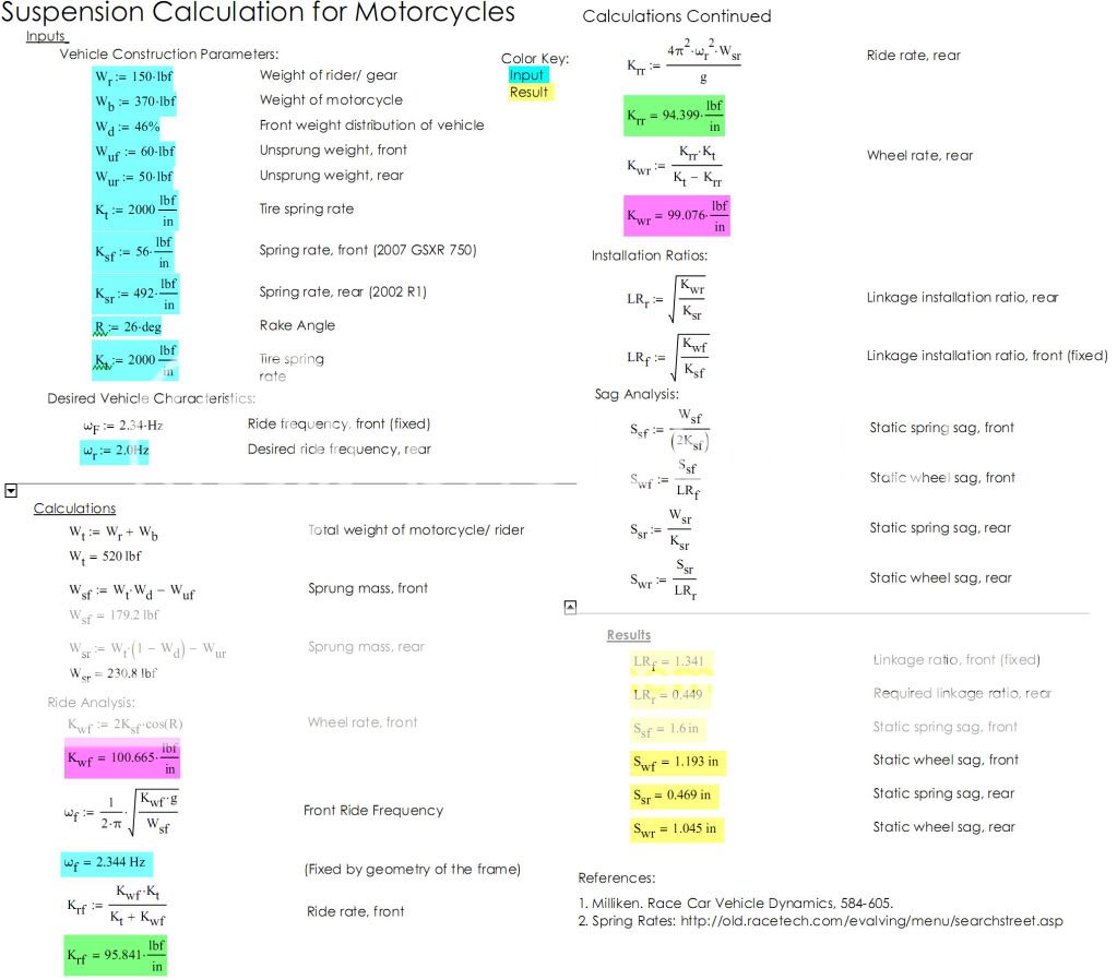
I am pretty happy with the numbers, but my only concern is the damping of the R1 shock. Looking at pictures and rough measurements of Bikebandit.com parts sheets, I am guessing that it had a stock motion ratio of about .2 ~ .25:1, which is about twice what I calculated to need. The wheel sag looks pretty good, so if the bike still maintains its 46% front weight bias, and I build everything tight enough, then the bike should sag evenly ;D Let me know what you guys think, maybe I am missing a blatant error or what not.
I pulled out my Race Car Vehicle Dynamics book from my suspension design days when I built Formula SAE race cars. This is my first shot at desgining for a motorcycle, but it is actually quite easier than a car...no roll gradients or other things like that to worry about. I collected all of the info and equations that I could and came up with this. All of this was done in a program called MathCAD, you basically write exactly what you want and it calculates it for you, very nice and easy, and it makes changing parameters very simple:
Note that the weight of the bike is an estimate based off of stock weight -expected weight savings. Also the tire spring rate is from what our race tires on the car were, but that doesn't affect the installation ratio at all. The picture is best viewed in its full resolution, sorry for the tiny words.
I am pretty happy with the numbers, but my only concern is the damping of the R1 shock. Looking at pictures and rough measurements of Bikebandit.com parts sheets, I am guessing that it had a stock motion ratio of about .2 ~ .25:1, which is about twice what I calculated to need. The wheel sag looks pretty good, so if the bike still maintains its 46% front weight bias, and I build everything tight enough, then the bike should sag evenly ;D Let me know what you guys think, maybe I am missing a blatant error or what not.
The Red Wonder
Been Around the Block
No body wants to check the suspension calcs...
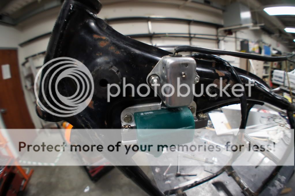
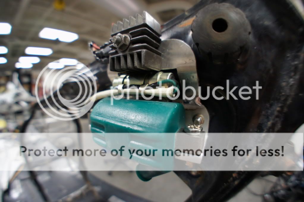
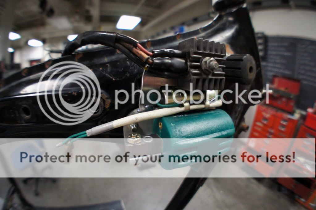
I made some pretty good progress yesterday. Fabbed up some mounts for all of the electronics and started on the gas tank.

Cut out the old gas cap

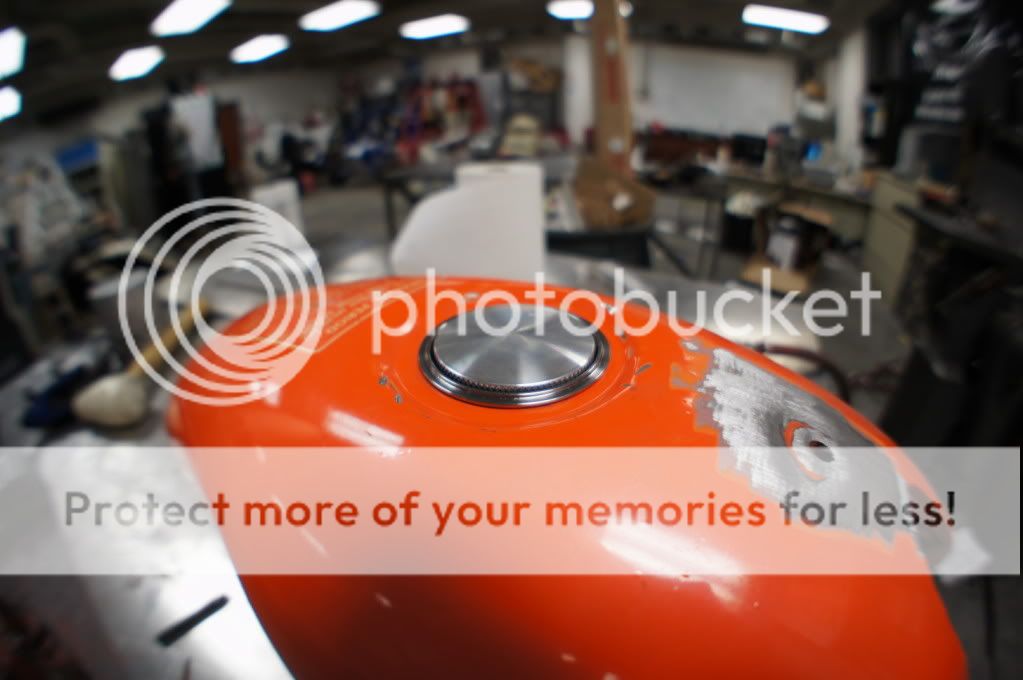
Opened the hole so the new gas cap fits in
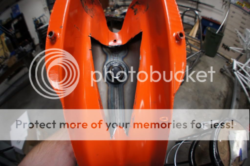
Welded the old mounting hole closed

Ground it clean. It still will need some bondo, I went back and forth a few times welding and grinding and I couldn't get it to where I liked it, so I will smooth it all out with bondo.

Welded in the gas cap, my TIG-ing still needs some help, but it is water tight on the first pass. I had cut an "O" out of sheet metal and was going to fit it over the tank and make everything flush but that I am pretty happy with how this came out. I will need to clean everything up more and probably use some bondo to shape it to where I want it.

I tried welding it from the inside the first time, but there wasn't enough room to maneuver the torch around.

This might need to be closed up...
Thanks for looking! Wishing all you guys a very Merry Christmas and happy holidays!
I made some pretty good progress yesterday. Fabbed up some mounts for all of the electronics and started on the gas tank.
Cut out the old gas cap
Opened the hole so the new gas cap fits in
Welded the old mounting hole closed
Ground it clean. It still will need some bondo, I went back and forth a few times welding and grinding and I couldn't get it to where I liked it, so I will smooth it all out with bondo.
Welded in the gas cap, my TIG-ing still needs some help, but it is water tight on the first pass. I had cut an "O" out of sheet metal and was going to fit it over the tank and make everything flush but that I am pretty happy with how this came out. I will need to clean everything up more and probably use some bondo to shape it to where I want it.
I tried welding it from the inside the first time, but there wasn't enough room to maneuver the torch around.
This might need to be closed up...
Thanks for looking! Wishing all you guys a very Merry Christmas and happy holidays!
The Red Wonder
Been Around the Block
jmemmert said:I am so jealous of your fab skills!! Keep it up man!
Thanks man, that I will!
sxecafe said:Wooooooooooo! Hard at work man. Love it.
What fish eye are you using to shoot?
Thanks! I am using a Sony NEX-5 with the 14mm pancake lens and Sony's Fish eye that screws in to that lens, its a reaaaal nice set up and super easy to use!
Here is a blog with a little info on it: http://sonyalphanex.blogspot.com/2010/10/sony-nex-vclecf1-fisheye-conversion-and.html
I GOT THE ENGINE HALF BACK! The first machine shop held on to it for a week and half then told me they weren't going to touch it
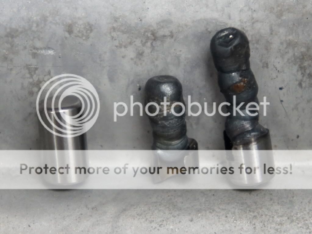
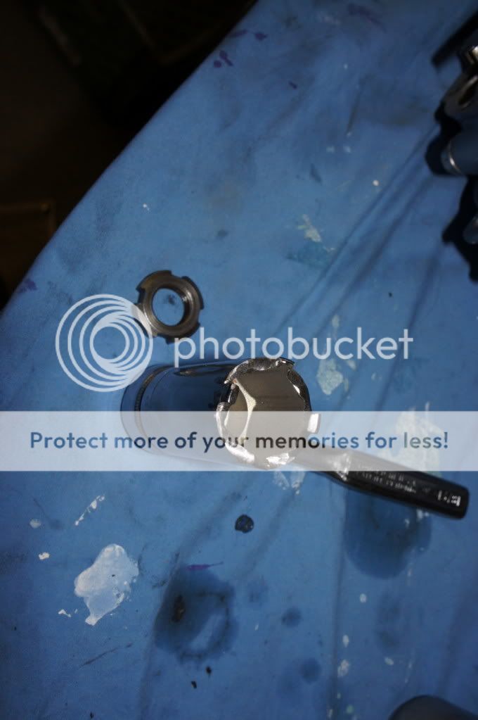
they then referred me to a guy a few block away who was able to get that stupid pin out in a day! He did what I was about to do, but wasn't sure if it was safe, he welded a blob of weld to the pin and then used vice grips to pull it out. The pin actually sheared in half the first time so he had to weld deeeep in the hole an even longer blob and was finally able to get it out... $20, two weeks, plenty of frustration, but its out and I can now re-assemble the engine! I still don't understand why this one was sooo stuck though, the new one slides right in and out ???
I should have the bottom end back together today and I still need to decide what to do about the cam/ head oiling situation...I had thought about the needle bearing conversion, but I spoke with Sean at Roc City quite a bit and he was super helpful, even drew up a new plan of how he would re-do it on his. My only concern however is that it is quite a bit of work, involving precision (.001") machining which I could do with enough time, heat treating of small parts ($$$), and cutting in to the threads of the head. I am not sure if all of this will pay off. I don't plan on holding the bike at redline or racing it, I still don't even have a MC license! I think I will drill the one hole in the center journal and call it a day. My dad is trying to assure me that Honda made tens of thousands of these bikes and with proper maintenance it should be fine, I agree with him for the most part....Thoughts?
Here you can see the sheared pin:
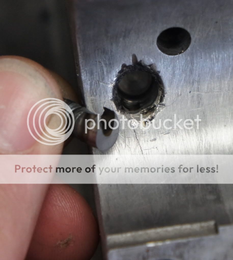
New pin, top of pin with weld blob 1, bottom of pin with LOOONG weld blob
This is the hole that I drilled before the carbide drill bit broke, mostly in the pin, but some in to the case :-\ it should be fine

RustyOlive
Been Around the Block
WOW!! those rear sets are wicked! nice job man!
I'll be for sure to follow your build.
Merry Christmas! ;-)
I'll be for sure to follow your build.
Merry Christmas! ;-)
The Red Wonder
Been Around the Block
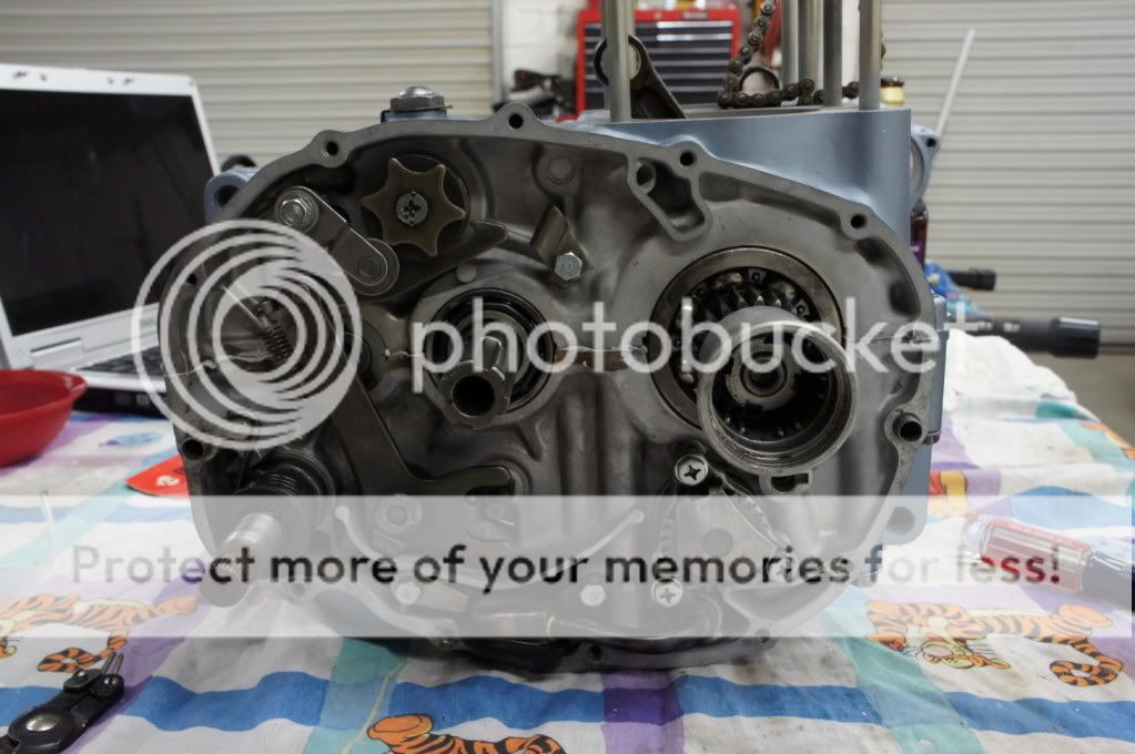
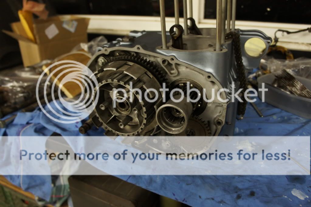
Made some more progress over the holiday. Glued the engine back together and then forgot about the clutch basket and the oil pump idler gear...so I had to find another "official" Craftsman 16mm lock nut tool, and by find I mean make.
Quickly realized I'm missing a few things!!
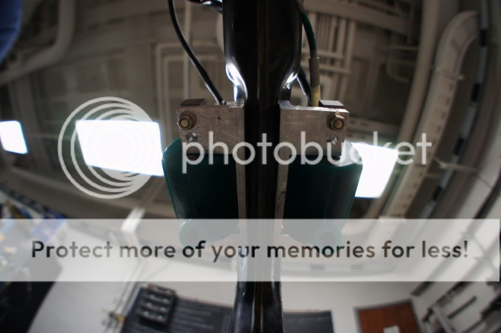
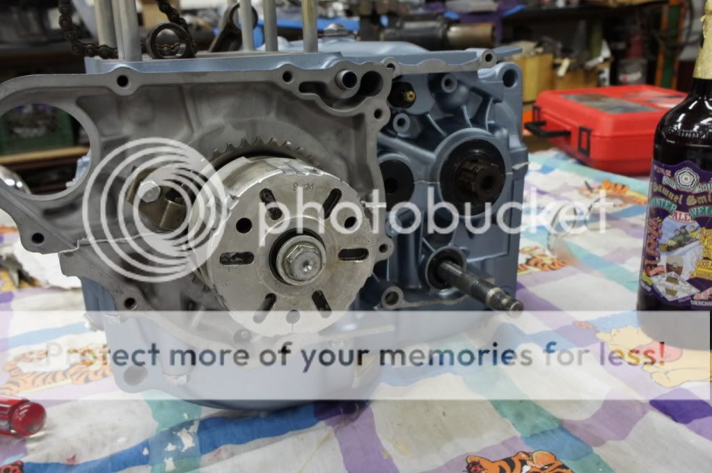
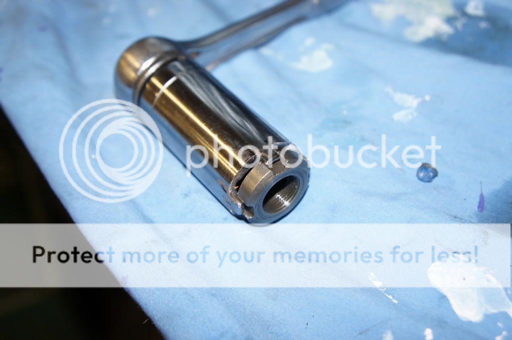
Extended dowel pins, they now bottom out fully and protrude from the surface about .050". Before adding the weld on the bottom, they would only stick up about .010". The chamfer on the needle bearing housing was bigger than that and not up to my standards. I am not sure if the guy or machine that drilled holes that day was high or what, but mine are definitely a little deep. These pins are now easy to get in and out and stick up high enough to positively lock those holders in place:

When I first made this, I had to guess on the width of the teeth, and luckily it kinda fit enough to get the nut off, then once it was out, I cleaned it up to where it fit nicely:
All back together and happy
Started on polishing. After making it through the 3 recommended wheels/compounds, I realized that I did not do near enough surface prep. There are still a bunch of scratches all over these things and the shine isn't what I was hoping for...sooooo I will have to go out and get the proper grit sand paper and re-do most of them, if not all of them.
Before
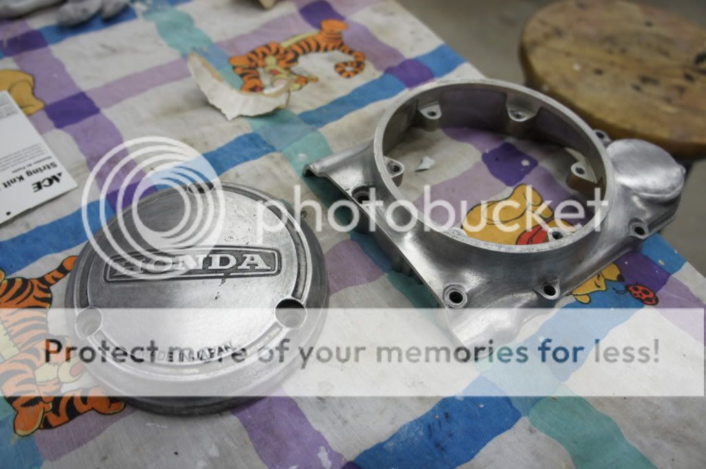
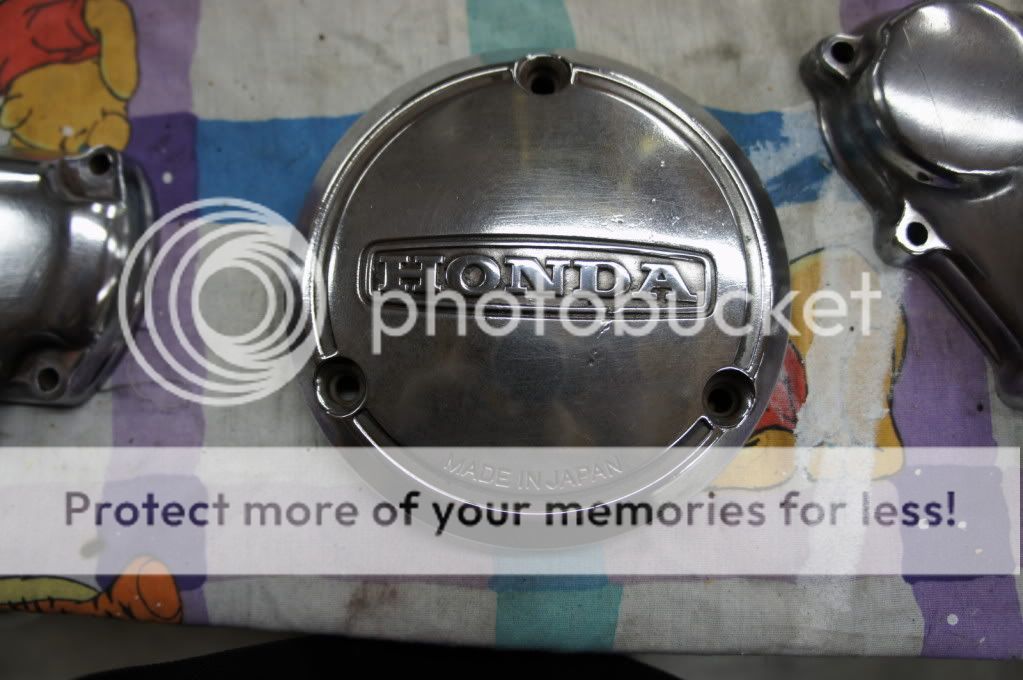
Points cover Stage 1, Breather cover stage 2:
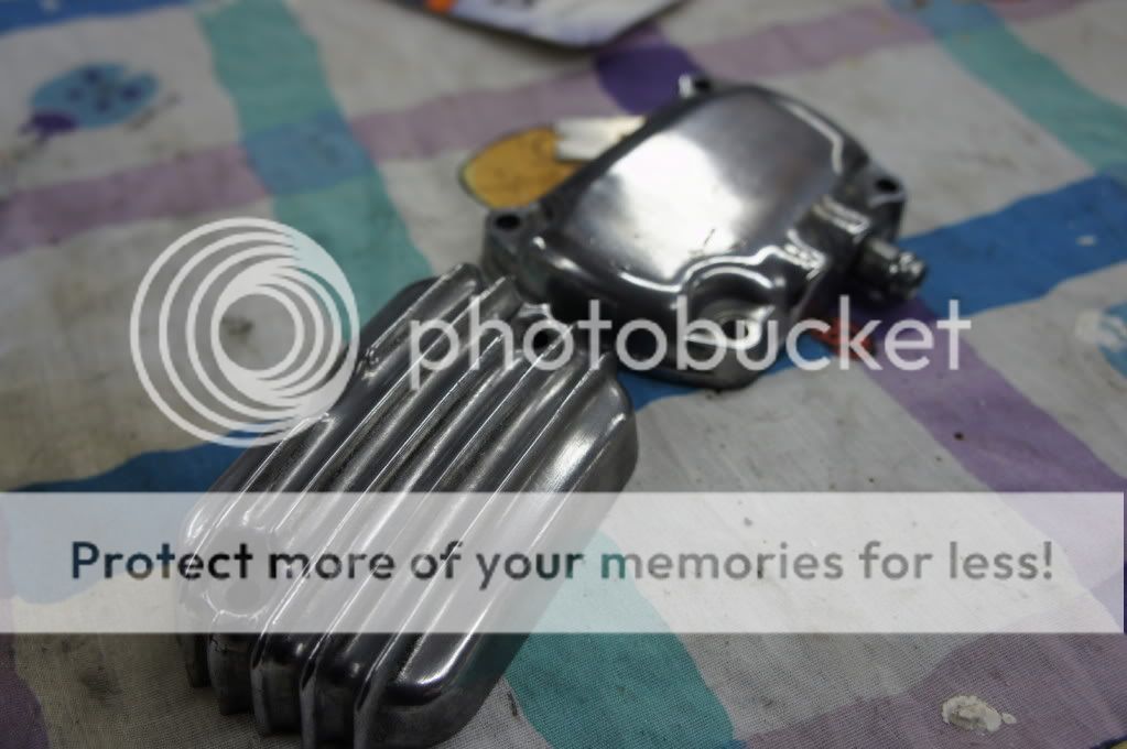
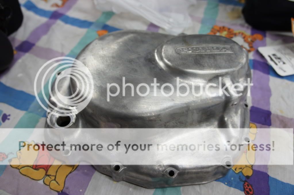
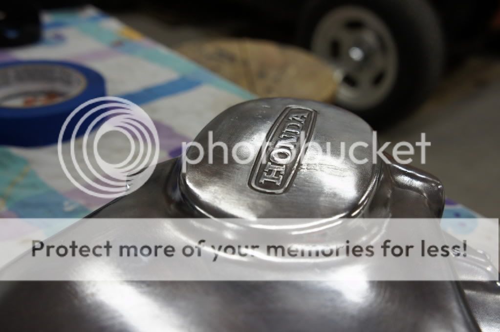
Stage 3:
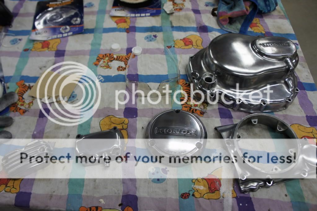
Tried to capture the scratches:
The mess behind the grinder

I wore a towel around my mouth...didn't wet it and now I am regretting that. I had chemical tasting burps for a few days after and my snot was black...definitely going to get a proper mask next time around!
Thanks for looking!
Quickly realized I'm missing a few things!!
Extended dowel pins, they now bottom out fully and protrude from the surface about .050". Before adding the weld on the bottom, they would only stick up about .010". The chamfer on the needle bearing housing was bigger than that and not up to my standards. I am not sure if the guy or machine that drilled holes that day was high or what, but mine are definitely a little deep. These pins are now easy to get in and out and stick up high enough to positively lock those holders in place:
When I first made this, I had to guess on the width of the teeth, and luckily it kinda fit enough to get the nut off, then once it was out, I cleaned it up to where it fit nicely:
All back together and happy
Started on polishing. After making it through the 3 recommended wheels/compounds, I realized that I did not do near enough surface prep. There are still a bunch of scratches all over these things and the shine isn't what I was hoping for...sooooo I will have to go out and get the proper grit sand paper and re-do most of them, if not all of them.
Before
Points cover Stage 1, Breather cover stage 2:
Stage 3:
Tried to capture the scratches:
The mess behind the grinder
I wore a towel around my mouth...didn't wet it and now I am regretting that. I had chemical tasting burps for a few days after and my snot was black...definitely going to get a proper mask next time around!
Thanks for looking!
The Red Wonder
Been Around the Block
crazypj said:I'm wearing a dual cartridge spray painters respirator while polishing, lots of dirt and dust flying around probably isn't very good for you
Yea definitely not, my dad has one, but I was looking at it and the diaphragm was warped to the point that it wouldn't do anything at all. It is on the "to-buy" list.
I first read that as "I'm wearing a dual cartridge spray painters respirator while POSTING", I laughed a little, then re-read it...lol.
The Red Wonder
Been Around the Block
sparkE said:any updates? This build is sweet, I love all the fab work.
On another note, I am getting started in SAE at my school, its a pretty awesome program. The knowledge I've been learning is great, and its cool to be able to build a car without having to pay for anything
Not as much as I would've liked. I got the materials for the swingarm so I am hoping to start on that this week as well as work on the tank some more.
SAE has been one of the greatest things for me so far. It has opened up more doors for my career than my education could have ever hoped to. I don't know what you mean about the "not paying for anything" though. Our team was on a TIIIIIGHT budget so a lot of it did end up coming out of our pockets, but it was worth it!
The Red Wonder
Been Around the Block
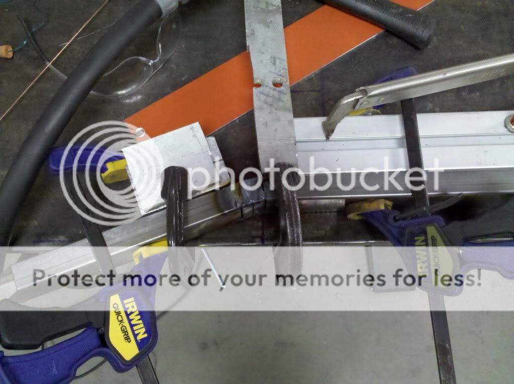
A bit of a baby update...I started work on the swingarm. Its using 2 " x 1" x .0625". These will bill the main legs that get welded to the old pivot. I just need to bend up a hoop and make a few support bars. I am snowboarding for the next week, so it will have to wait
You can never have too many clamps! These were intended to be a 19* bend, but after welding came out closer to 20.5* which is a pretty decent tolerance in my books.
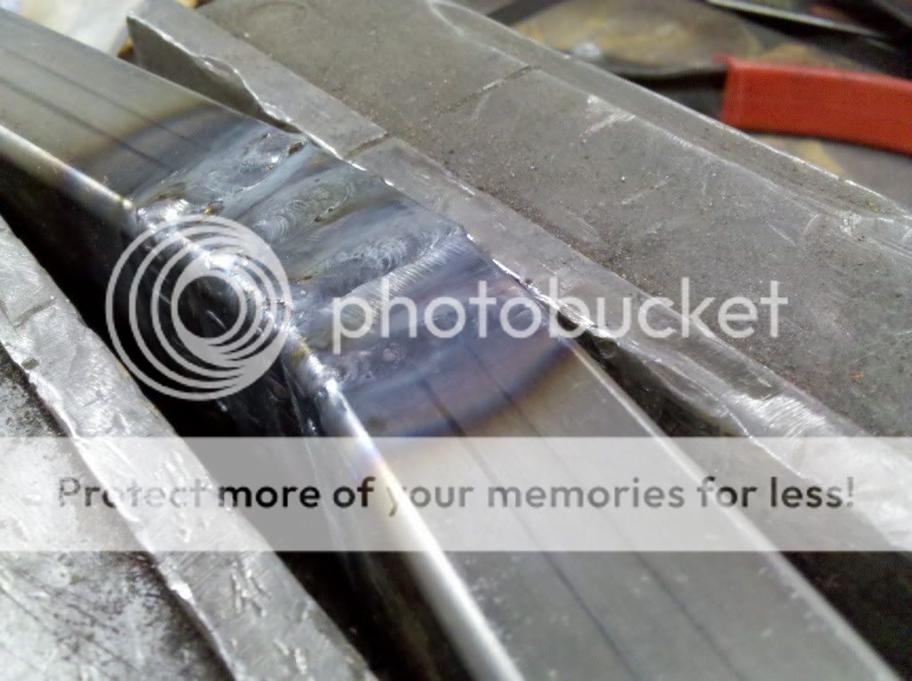
Cut some slits and bend, then re-weld. Some welds definitely better than others...
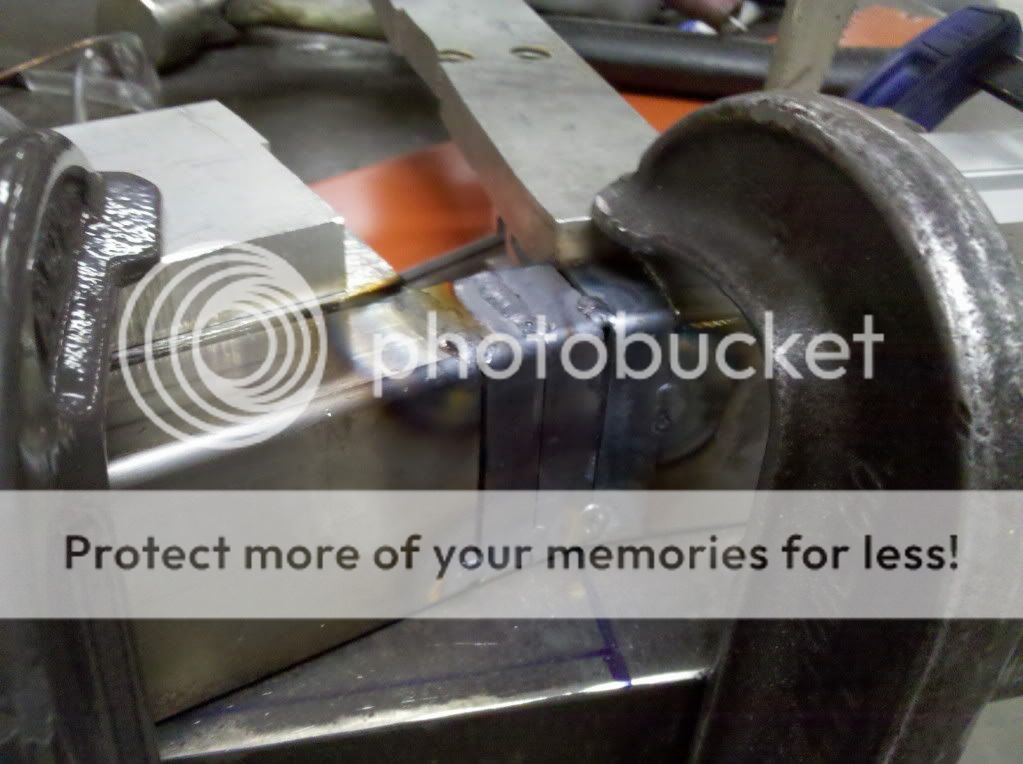
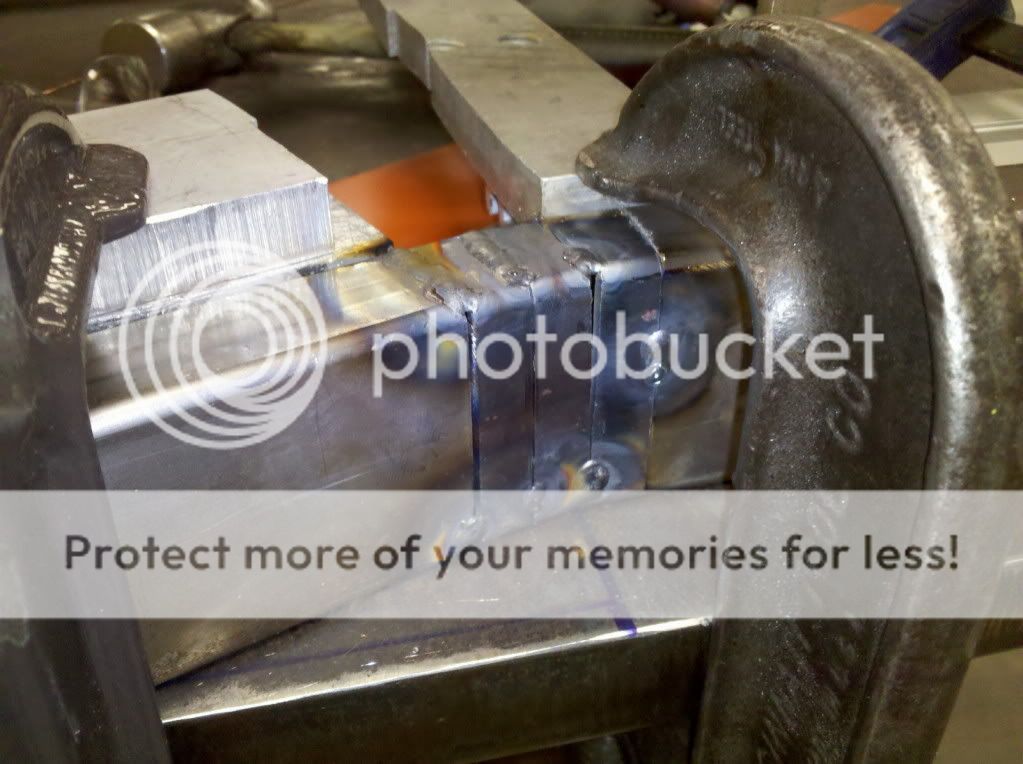
Squezzed in a vice in an attempt to relax the weld a little closer to 19*...didn't do anything...I guess that means it stiff!
Welp, I hope you guys enjoy the baby update for now! Thanks for looking
You can never have too many clamps! These were intended to be a 19* bend, but after welding came out closer to 20.5* which is a pretty decent tolerance in my books.
Cut some slits and bend, then re-weld. Some welds definitely better than others...
Squezzed in a vice in an attempt to relax the weld a little closer to 19*...didn't do anything...I guess that means it stiff!
Welp, I hope you guys enjoy the baby update for now! Thanks for looking
thompsonmx100
Over 1,000 Posts
Cool I like the baby update. I like the idea for the swingarm. I would recommend running another pass over those welds. They look good but you did have some pretty big gaps. Just what I would do. Keep it up love this bike.
The Red Wonder
Been Around the Block
Thanks, I'm glad you like it! That's is a good idea. This was just a first pass. I'm going to grind it down smooth because the welds look like poop. Then I'll probably have to add some more weld in the sinks. I'm not worried about strength, those legs won't be as highly stressed as the round tubes that support the shock. I had full penetration on the welds so you can't ask for much more. Pilling weld on top won't add any strength, only extra material. Unlike aluminum, a properly welded joint in steel is stronger than the steel itself. Thanks for the idea!


