Honda XR650L Thumpster

compoundcycles said:
Thanks for all the feedback and suggestions.

How would you guys go about lowering the front forks? Anyone know of a thread where someone has done this? Thanks.
I'd go internal lowering, there are plenty of threads like that, but as I don't know how your fork internally design I can't add more to this.

Sent from my GT-I9300 using Tapatalk
 
compoundcycles said:
How would you guys go about lowering the front forks? Anyone know of a thread where someone has done this? Thanks.

I've lowered several sets of conventional "right-side-up" damper-rod forks with zero issues, including the same Showas on your and my XR's. As long as you're comfortable with basic general fork disassembly/reassembly, changing seals, bushings, springs, etc., then lowering the forks will be a cinch.

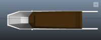
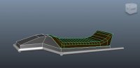
First, study the pictures on this page thoroughly, or even better, print it out for reference. The text applies to fitting Race-Tech valve emulators (which you may or may not care about), but the diagrams are very clear and uncomplicated.

The XR Showas have a few more additional internal components than those shown in the drawings, but the same basic principles apply with regards to lowering the forks.

Look at the cross-sectional drawing and notice the position of the main spring in the upper portion of the fork tube, and the top-out spring in the lower section of the fork tube. Also look at the spacer between the top of the main spring and the bottom of the top cap. Not all forks will have a spacer there. Some forks will have some sort of adjuster built-in to the top cap that presses down on this spacer, or directly on the spring itself (no spacer).

I'm not sure if the stock XR forks have a spacer or not; my bike came to me with aftermarket springs installed, and spacers above those springs. All else being equal, longer top spacers = more spring preload, and shorter top spacers = less spring preload. (I think this is why many aftermarket springs come with spacers or spacer material; it allows you to set your initial preload by changing the spacer length).

To lower the forks, you remove length from the top spacer and add an identical length to the top-out spring. Generally, you can use the same size material for both locations. My aftermarket springs came installed with 3" spacers above them. This was ideal, as I wanted to lower the front approx. 3"! I simply moved the top spacer from the above the main spring to above the top-out spring. Both your ride height and your total available fork travel will be reduced by a corresponding length.

So that's it: just remove length from the top spacer and add it to the length of the top-out spring. If you have no top spacer (ie., the main spring rides directly on the top cap and/or top adjuster), you will have to cut your main spring down. Whatever amount you cut out of the main spring, add it to the top-out spring. The spacer material you use can be just about anything that will fit, as long as it is a slip-fit, strong in compression, and doesn't fill the space so completely as to impede oil flow. I've used thin-wall alloy tubing, PVC pipe, and machined aluminium spacers.

Some forks don't have top-out springs. In this case, add length to where the top-out spring would be if there was one. If you want to get fancy, you can add a top-out spring with careful measuring. For instance, when I lowered my stock XS650 forks, I cut 2-1/4" off of my main springs, then added a top-out spring with a 1-14" compressed length with a 1"spacer above it. My ride height was closer to 2-5/8" down from stock, but by using the compressed length of the top-out as a starting point, I guaranteed that I wouldn't have a "dead band" in my fork travel.

The exact interplay of tubes, rods, and pistons is almost impossible to explain and difficult to visualize, but once you have all the parts in your hands and finally "get it", you'll see that it's actually fairly simple.

Again, all of this assumes you're comfortable with basic damper-rod fork internal geometry, and basic assembly/disassembly. Internaly-lowering a rear shock is functionally simpler, but mechanically more difficult; let me know if/when you get to that stage...
 
Thanks so much for the info. I was planning on lowering the rear with a lowering link. So the rear would come down 1in and the front I would probably lower 2-3in. I still need to take some better measurements.
 
compoundcycles said:
Thanks so much for the info. I was planning on lowering the rear with a lowering link. So the rear would come down 1in and the front I would probably lower 2-3in. I still need to take some better measurements.

I used a Kouba Link on the rear for 1-3/4" lowering, plus an additional 10mm internal shock lowering for approx 2-3/4" total in the rear. As stated above, went with 3" lower in the front. That, and a 19" front wheel should make for more street-friendly geometry.
 
To get a better idea of how I would layout the seat frame I mocked up my plan in Maya. I like the layout of the frame tubes but I think eventually the cowl and seat will be higher. I eventually will want to stash the battery inside the cowl, unless the battery will fit in the electronics tray under the seat. This gives me a good idea of the footprint though. It also helped me figure out how I'm going to mount the mufflers while keeping the lines I want.
 

Attachments

  • side.jpg
    side.jpg
    66.1 KB · Views: 368
  • top.jpg
    top.jpg
    21.6 KB · Views: 347
  • 3QUARTERS.jpg
    3QUARTERS.jpg
    69.6 KB · Views: 361
  • closeup.jpg
    closeup.jpg
    23.6 KB · Views: 373
Here's part of the frame cut and welded up. Still need to work on the talk section.
 

Attachments

  • uploadfromtaptalk1412995978637.jpg
    uploadfromtaptalk1412995978637.jpg
    2.3 MB · Views: 370
  • uploadfromtaptalk1412995941618.jpg
    uploadfromtaptalk1412995941618.jpg
    1.6 MB · Views: 396
  • uploadfromtaptalk1412995879948.jpg
    uploadfromtaptalk1412995879948.jpg
    846.7 KB · Views: 438
  • uploadfromtaptalk1412995835896.jpg
    uploadfromtaptalk1412995835896.jpg
    1.7 MB · Views: 414
Thanks guys!

I worked some more on the seat and frame today. Kept trying to get the angles right and I think I found something that works so I welded it up. My welding leaves something to be desired but it'll hold. I didn't quite make the same lines with my final tail piece as I mocked up in 3D because when I tacked the tube on in that position it just didn't look right.

My denim welding jacket gave me a hand covering the rear tire and mufflers.
 

Attachments

  • uploadfromtaptalk1413341372564.jpg
    uploadfromtaptalk1413341372564.jpg
    1.8 MB · Views: 383
  • uploadfromtaptalk1413341431138.jpg
    uploadfromtaptalk1413341431138.jpg
    1.9 MB · Views: 373
  • uploadfromtaptalk1413341716049.jpg
    uploadfromtaptalk1413341716049.jpg
    1.8 MB · Views: 406
  • uploadfromtaptalk1413341779252.jpg
    uploadfromtaptalk1413341779252.jpg
    1.7 MB · Views: 414
I got out the nice camera since finishing the frame is somewhat of a milestone.

I threw the cb360 tank back on to see where I'm at. The tank needs to be lowered overall, and a bit more in the front to hit the lines of the seat but I think I can make it work nicely in the end. Banging out the dents in the tank has me more nervous.
 

Attachments

  • seat_frame-004.jpg
    seat_frame-004.jpg
    358.3 KB · Views: 383
  • seat_frame-003.jpg
    seat_frame-003.jpg
    610.3 KB · Views: 398
  • seat_frame-002.jpg
    seat_frame-002.jpg
    378.5 KB · Views: 1,480
  • seat_frame-001.jpg
    seat_frame-001.jpg
    356 KB · Views: 390
While I was waiting for some welds to cool I banged up something to fill the negative space in between the seat and the downtubes. I think it's 20g stainless mesh. This specific piece was just a test.

You can see the section of the hodaka tank that was remove still tacked to my welding table, and the jig I used to hold my seat tube while rounding in the ends on the drill press.
 

Attachments

  • seat_frame-006.jpg
    seat_frame-006.jpg
    364 KB · Views: 377
  • seat_frame-007.jpg
    seat_frame-007.jpg
    516.8 KB · Views: 382
  • seat_frame-008.jpg
    seat_frame-008.jpg
    426.7 KB · Views: 383
  • seat_frame-009.jpg
    seat_frame-009.jpg
    373.7 KB · Views: 1,449
Gratuitous workshop shots...
 

Attachments

  • seat_frame-013.jpg
    seat_frame-013.jpg
    556.6 KB · Views: 1,453
  • seat_frame-012.jpg
    seat_frame-012.jpg
    484.9 KB · Views: 384
  • seat_frame-011.jpg
    seat_frame-011.jpg
    638.2 KB · Views: 410
  • seat_frame-010.jpg
    seat_frame-010.jpg
    582.8 KB · Views: 1,471
Thanks Guys!

I lowered the tank to better hug the lines of the frame. I'll post more pics of the process soon (it wasn't pretty). I think the tail of the tank needs to be raised about 0.5", right not the front is still a touch higher.

Also, I'm becoming concerned that my seat frame is not sturdy enough. I think the tail, especially when I push down on it with my hands is flexing too much. I think I'm going to add another support to feel confident when riding it. I love the minimal look to it now, but safety first. Had I used 1" tube instead of 3/4" i might feel better.
 

Attachments

  • tank_lower-001.jpg
    tank_lower-001.jpg
    439.1 KB · Views: 396
  • tank_lower-002.jpg
    tank_lower-002.jpg
    498.4 KB · Views: 387
  • tank_lower-004.jpg
    tank_lower-004.jpg
    471.9 KB · Views: 377
  • tank_lower-005.jpg
    tank_lower-005.jpg
    458.6 KB · Views: 403
I'm sad to go down this route but here's what I was thinking for more seat support. Please let me know if anyone has any better ideas. It's not that I'm afraid the seat will snap while riding, but over time I'm afraid the seat might start to bend a bit. Maybe it won't feel so flexible once I have a electronics tray mounted in and a seat tying it all together.
 

Attachments

  • frame_brace.jpg
    frame_brace.jpg
    72.8 KB · Views: 413
I would just replace the lower bar further back so that it is under where you sit. Then add some gusset plates in and you should be right. Replace the bar with 1" for peace of mind haha.

Here is a terrible photoshop I did on ny phone.
 

Attachments

  • uploadfromtaptalk1413679193107.jpeg
    uploadfromtaptalk1413679193107.jpeg
    424.2 KB · Views: 366
This suggestion also looks really good as the new position of the tube is parallel Tu que Exhaust angles on the back and also on the front (header pipes)

Sent from my GT-I9300 using Tapatalk
 
Either Brodie's suggestion or similarly bring the angle on the down tube further. You could also mount a brace plate at the underside of the angled tube.
 

Attachments

  • frame_brace.jpg_thumb.png
    frame_brace.jpg_thumb.png
    418.3 KB · Views: 1,249
Back
Top Bottom