Follow along with the video below to see how to install our site as a web app on your home screen.
Note: This feature may not be available in some browsers.
We noticed you are blocking ads. DO THE TON only works with community supporters. Most are active members of the site with small businesses. Please consider disabling your ad blocking tool and checking out the businesses that help keep our site up and free.
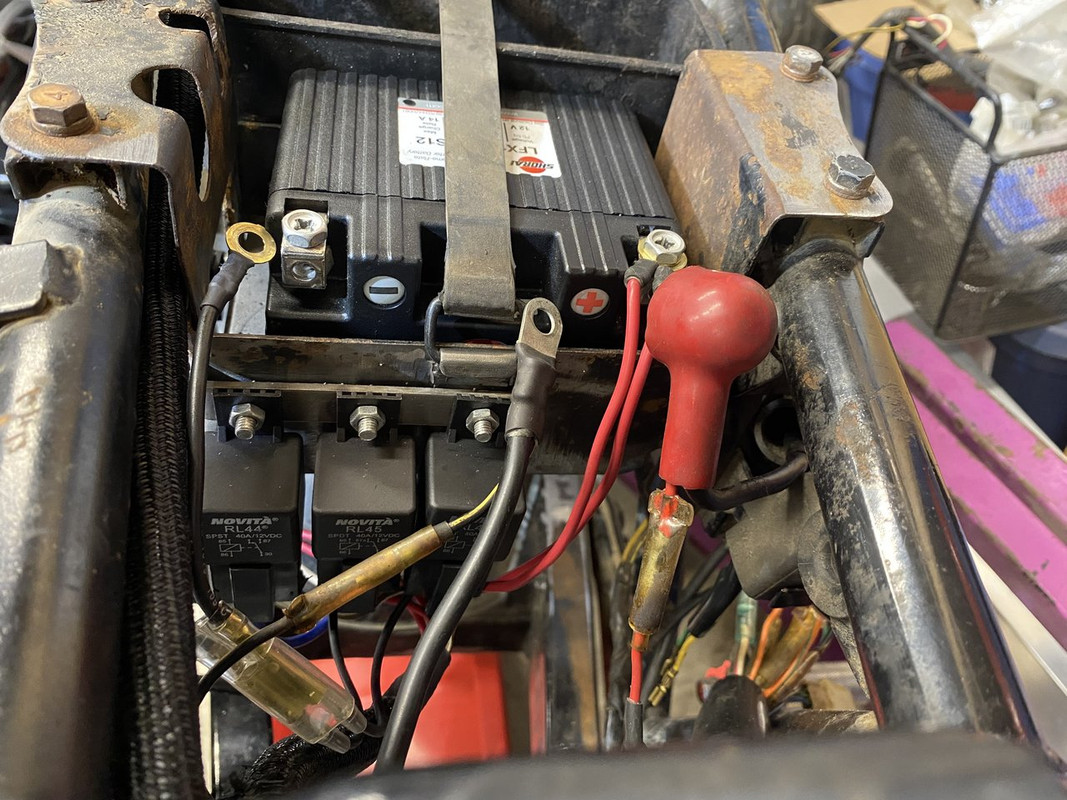
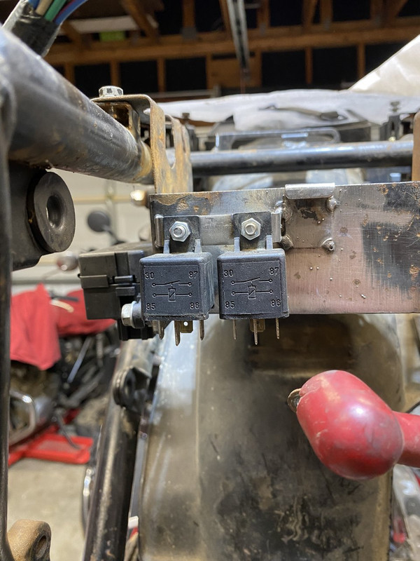
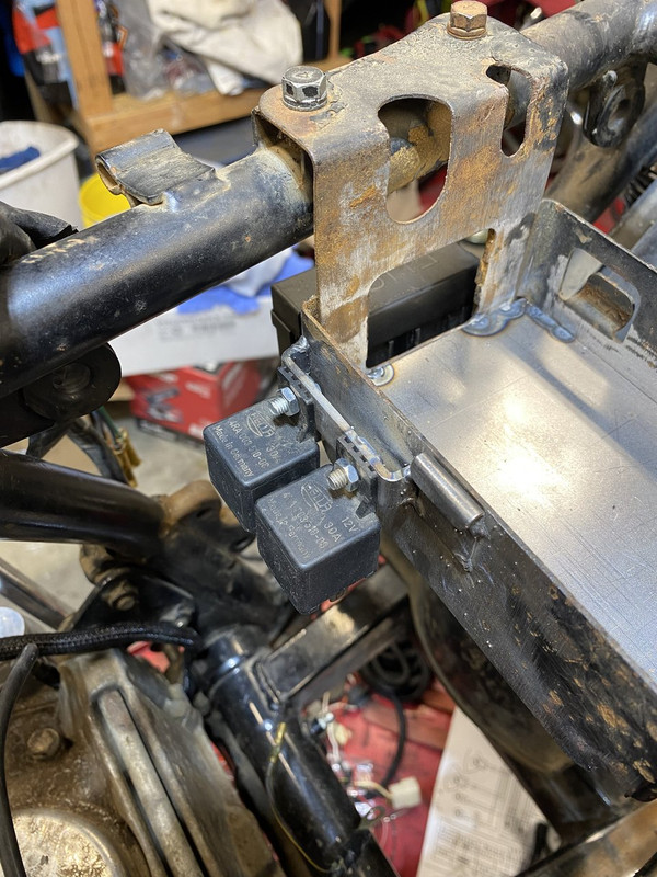
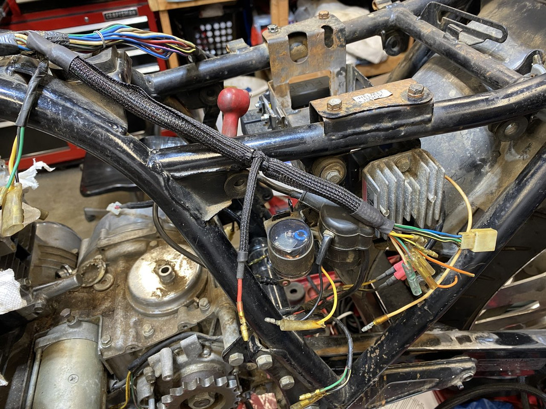
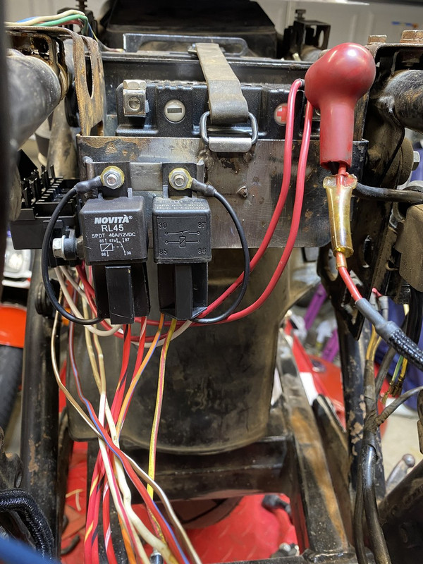
I think the battery box is finished minus paint and adding foam for the battery. I ended up adding a small bar with two studs for the relays I’m adding in. One SPST for the coils and a SPDT for the headlight. Each will have it’s own fuse in the fusebox.
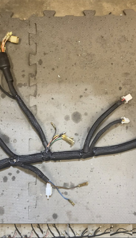
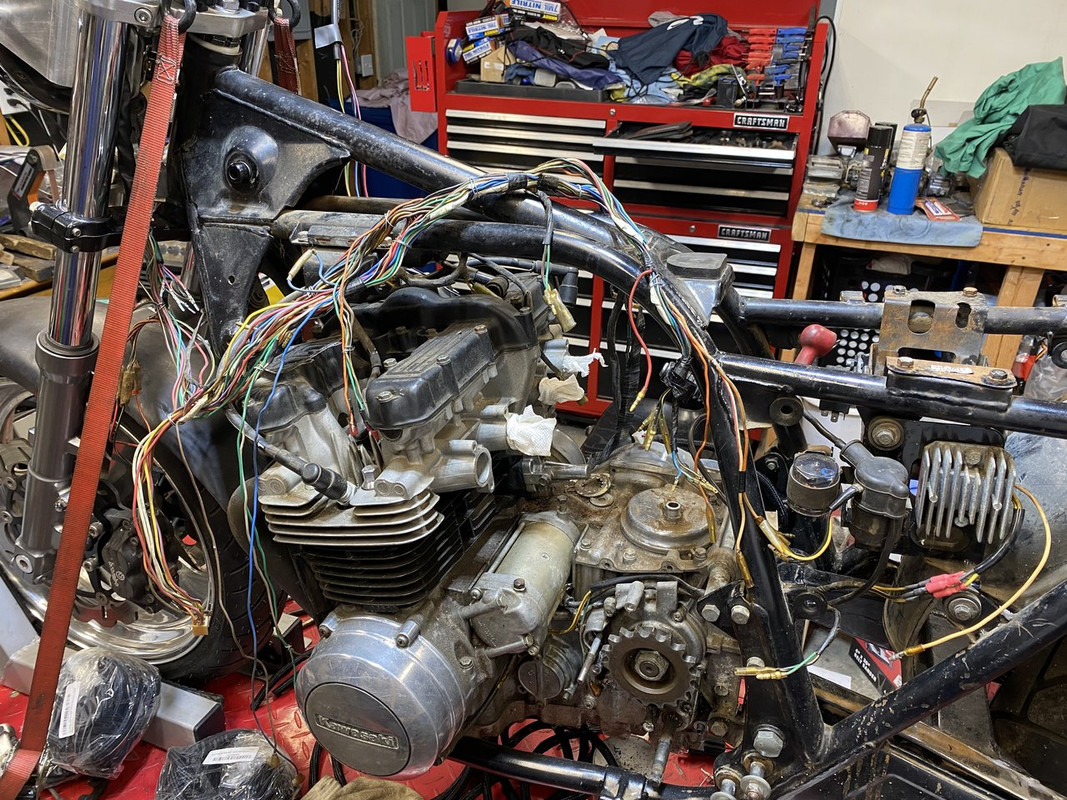
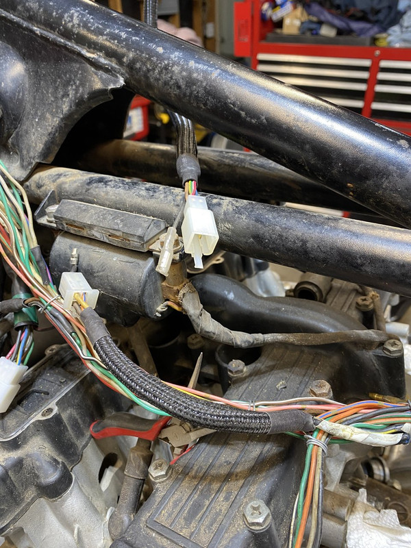
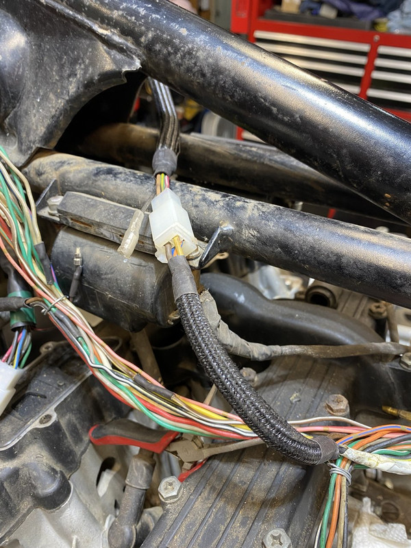
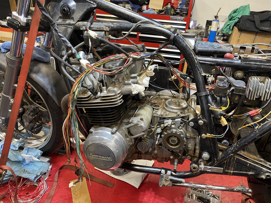
I started unwrapping the harness to chase down the extra wires for the second turn-signal/hazard relay. The Zx14 switch takes care of it internally so a second relay is redundant. I’m using the same style harness wrap and heat shrink tubing like I did with the DynaS.
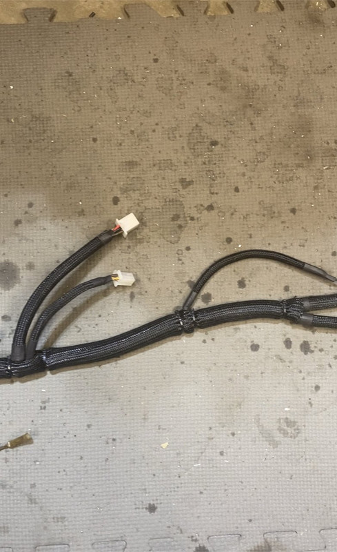
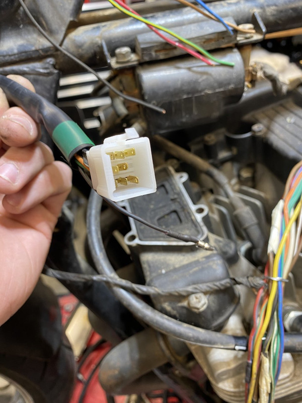
More wiring competed. I think I have everything planned out. Just waiting on some correct colored wire to arrive for the main harness so I can keep constant with the Kawi wiring diagram. Right and left side switches are wired with new terminals and connectors.
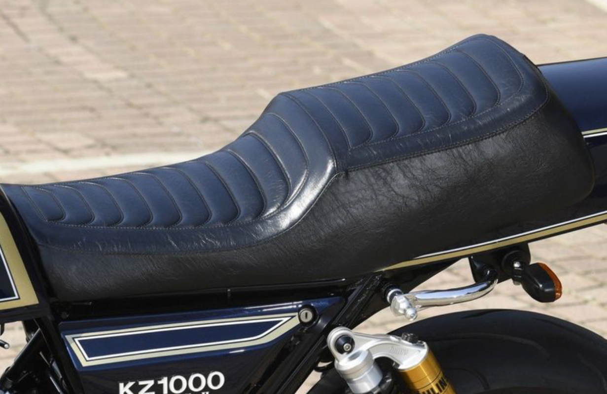
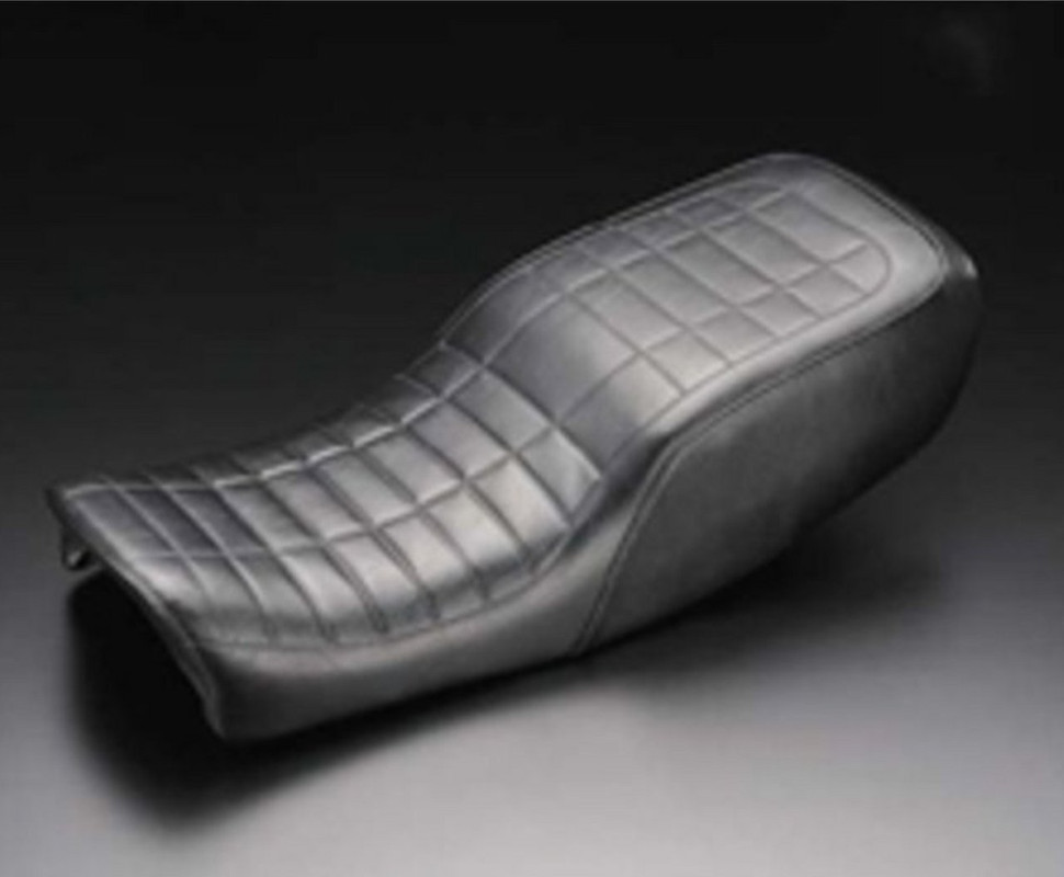
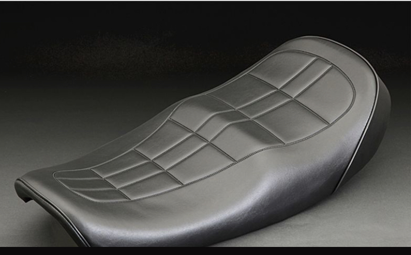
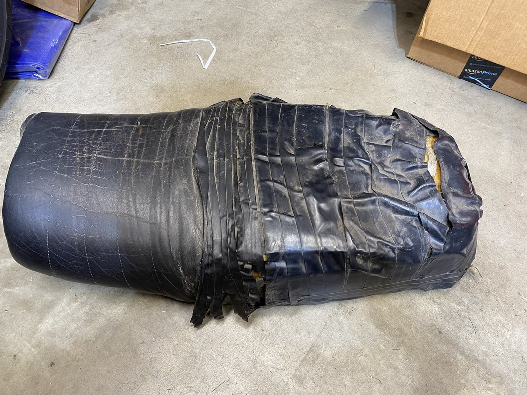
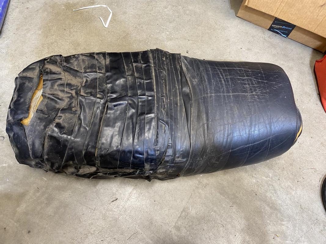
I’ve been working on another bike for a guy so not much progress. But, I was able to pick up another seat in trade for some left over parts from the build. The cover is crap, but I ordered a repro stock cover so no worries there. The pan is about. 8/10 with a single small crack. My ultimate plan is to make a seat like the examples below. No one that I can find makes something similar for the 650’s; just the 900/1000’s.
Here’s what I’m starting with.
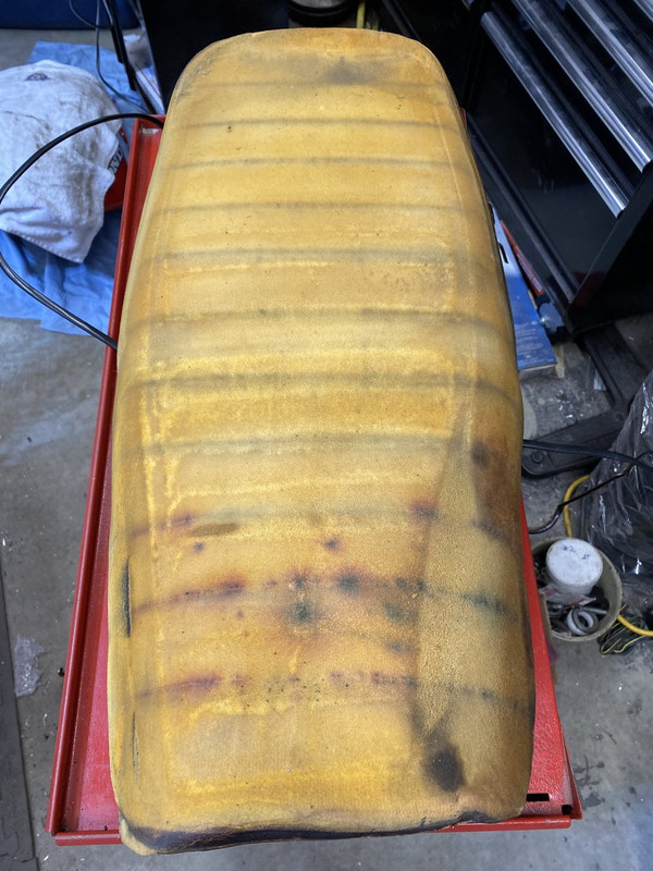
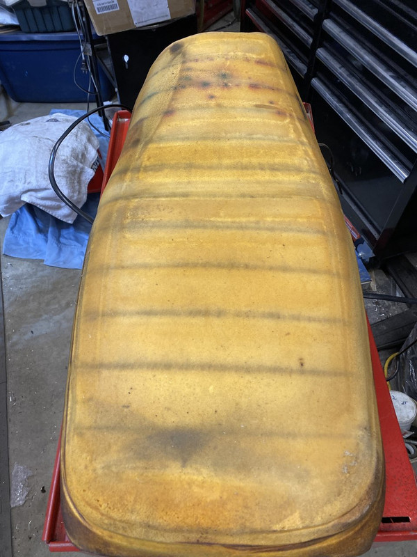
Tips or suggestions on shaving down the foam would be great. I’ve heard of electric carving knife or a grinder with sanding disc (messy?). Would like thoughts on adding a gel insert, too.
I use a serrated bread knife. I use a closed cell foam kneeling pad as an insert a lot and just trace the shape on the old foam then cut it out and lay it in the hole. My last seat I just completely replaced the foam with 2 layers of the pad and then a small bit of a lower density foam layer on top.
A file sander works great for fine shaping. I have a short one that runs a 3/8 x 13 inch belt but if you could get a hold of one that runs a 3/8 x 18 that would be even better. A long knife with a fresh ground edge works like a serrated knife for hacking off bigger pieces. Be extremely cautious using an angle grinder! It will move a lot of material but also will snag and run into things you don't want it to run into like your hand, don't ask me how I know.
Electric carving knife from ebay (NOT the wife's!) works great. And like Maritime sez - a thin layer of soft foam to "skin" it really smooths the look of the final upholstery.
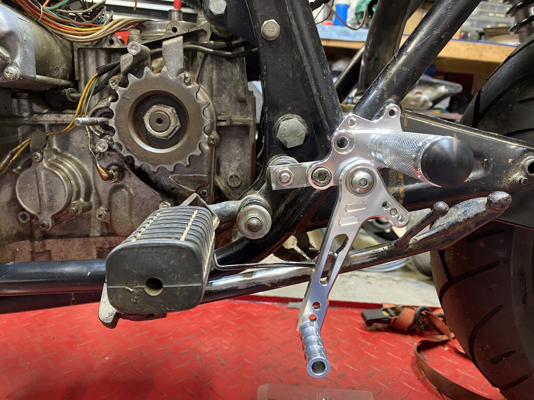
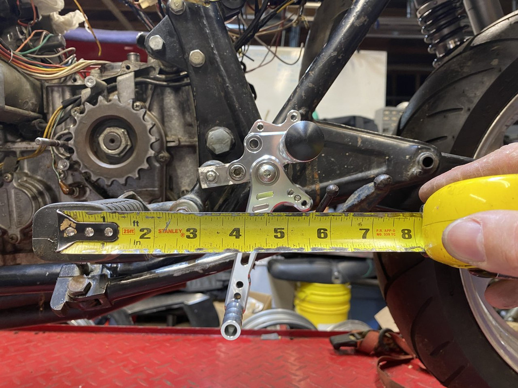
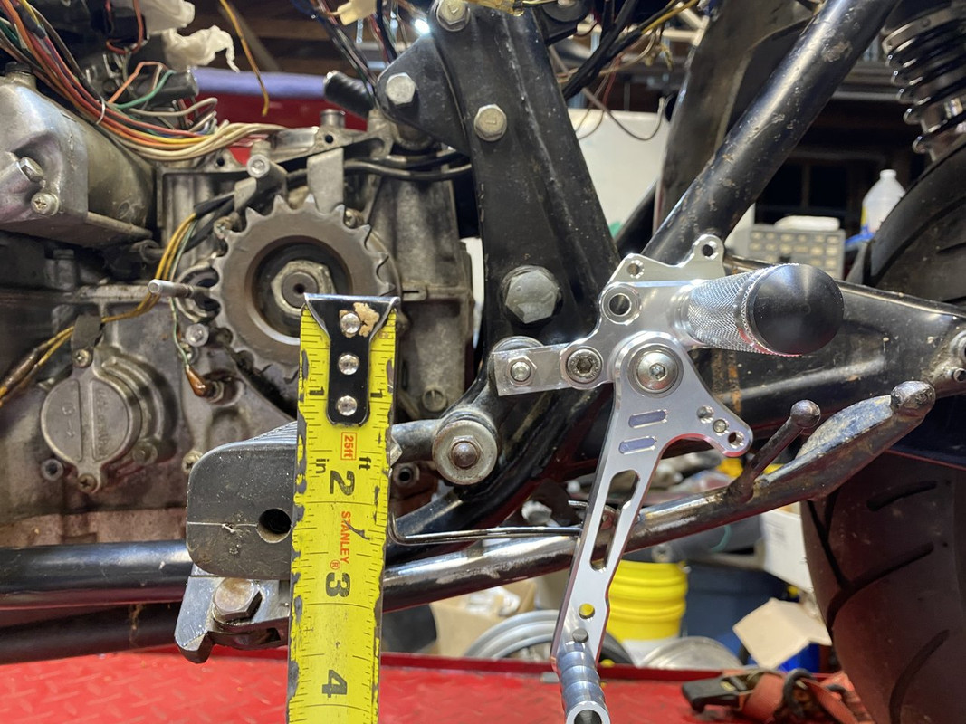
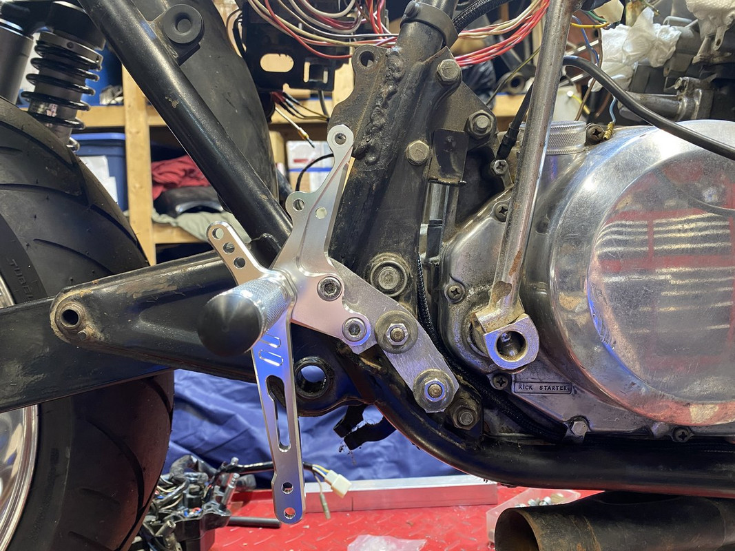
Not much to report, but made a little time to start finalizing my rearset positioning. Not sure if I’m set on the location just yet. I may make the adapter plates needed with 2 or 3 different mounting possibilities for some adjustment…we’ll see. I’ll have to offset the pegs about 2” out from the frame so that the shift lever clears the sidestand. Just eye-balling it, the left engine cover will make ground contact about the same time the footpeg will.
I did give that option a thought, but that’s a more invasive surgery than I want to do with this project.
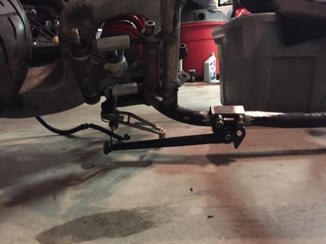
I removed the factory mount on my Gpz750 and made my own mount with a newer Ninja sidestand for the rearsets on it. Crappy pic, but shows what I came up with.
I made a print to machine out my rearset adapters. Good thing I plotted it at a scale of 1:1 as the OE mounting holes were WAY off! I think I adjusted the dims correctly so I’ll print it out at scale and try again.
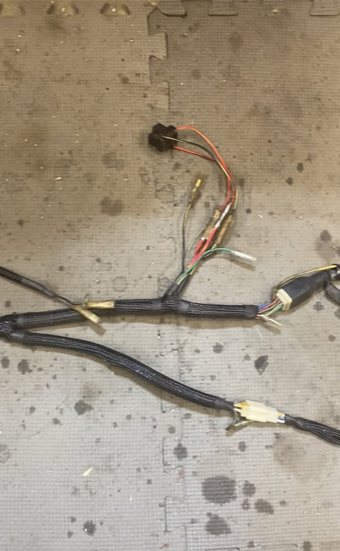
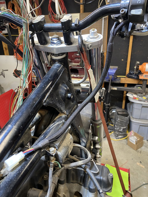
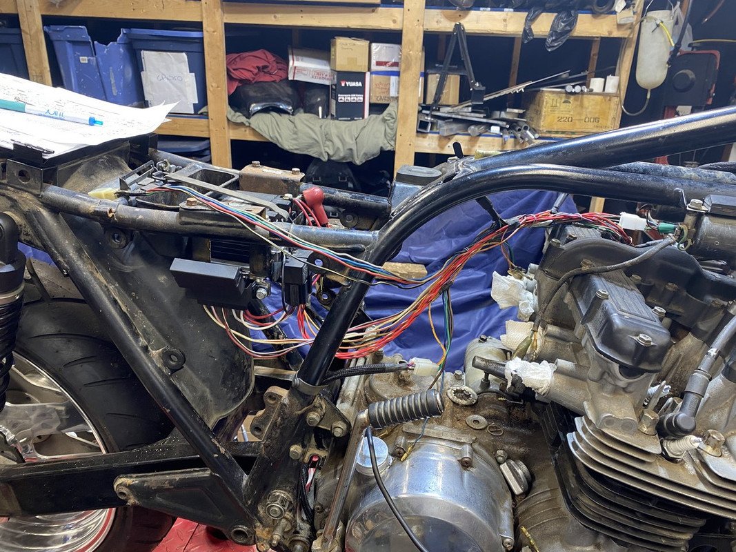
Back to the wiring… I almost got the harness finalized. I have to purchase a couple small terminals and add a short branch to the main ground circuit then testing before completing the covering and wrapping.
I couldn’t get the holes to line up quite right with my 1:1 drawing as my measurements weren’t as accurate as I thought. I abandoned the print idea and decided the old school method of transfer punching and drilling holes in scrap plate is easier and a bit more accurate.
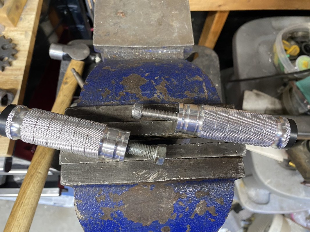
While I was at it, I drilled and tapped the pegs for M10 bolts. The rearsets originally use M8 hardware and even sleeve down a 10mm ID bearing to 8mm because of it.
I still want to tweak the peg and hole locations a small amount as well as design a tidy method to offset the brackets away from the frame. That will probably consist of round spacers with some registers so the load isn’t completely on the hardware.
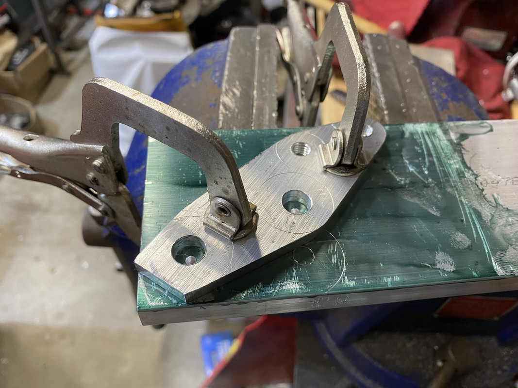
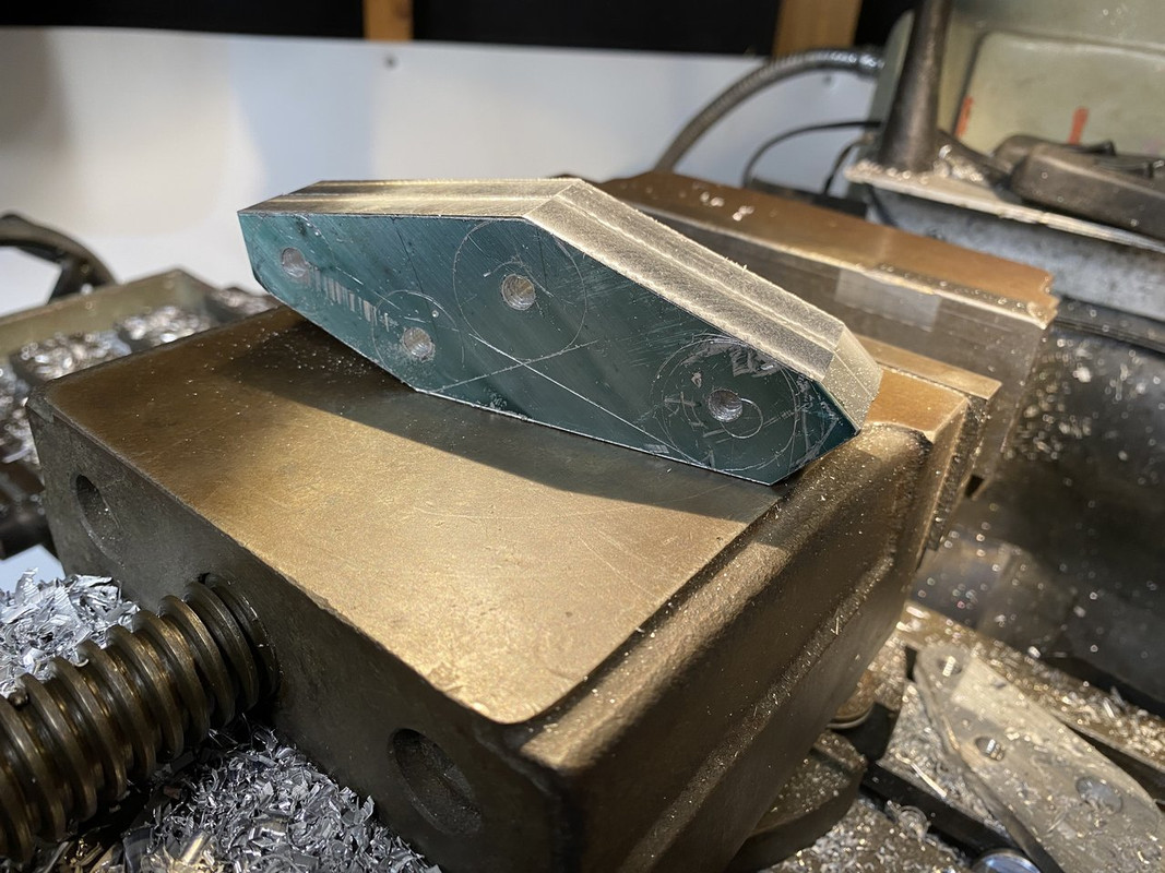
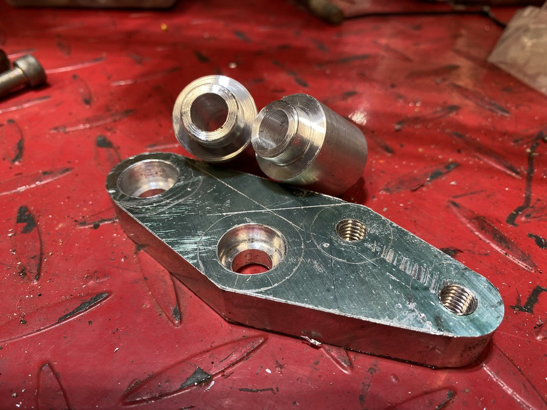
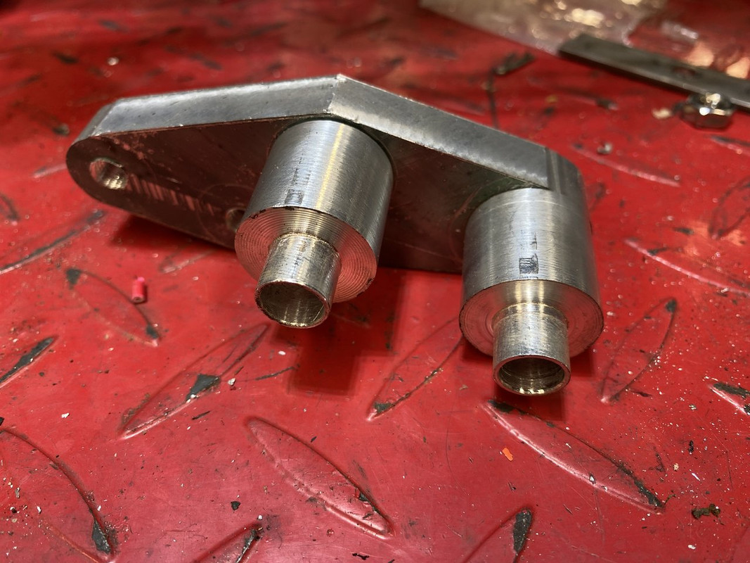
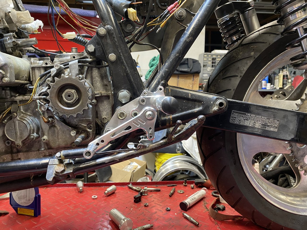
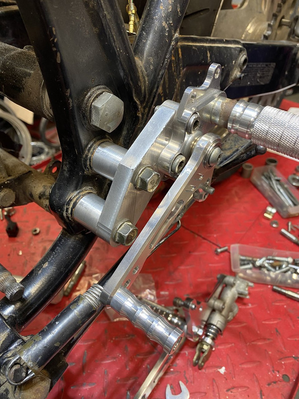
I made one last template and got all the holes to line up where I wanted/needed them. I transferred the locations to some 1/2”x 3” 6061 bar and started carving the shape out.
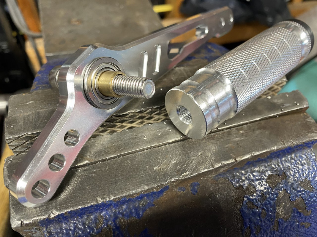
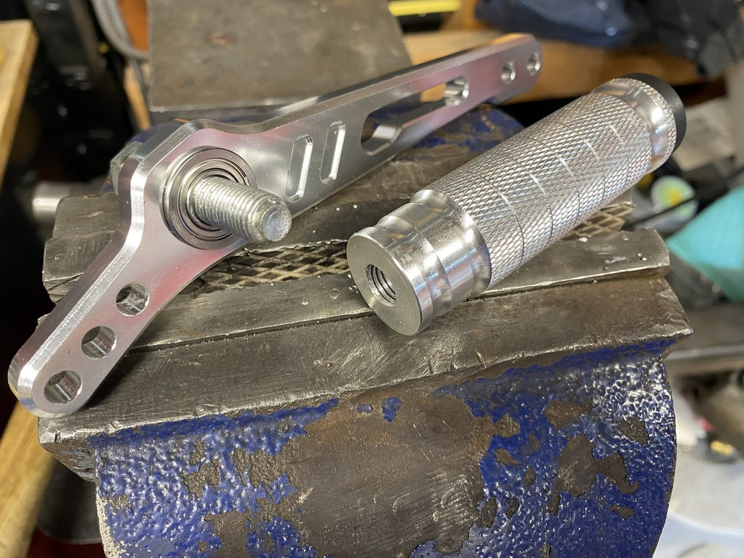
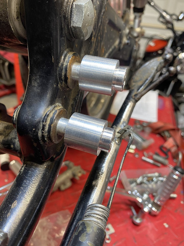
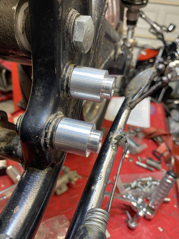
Next I turned up the required spacers. I added a boss on each end. The stock peg studs have a 12mm diameter shoulder and 10mm threads, so I replicated the same setup on one end but with a 10mm through hole. The other I turned a 5/8” diameter boss to match a 5/8” end mill I had. The spacers offset the adapter plates 7/8” from the frame.
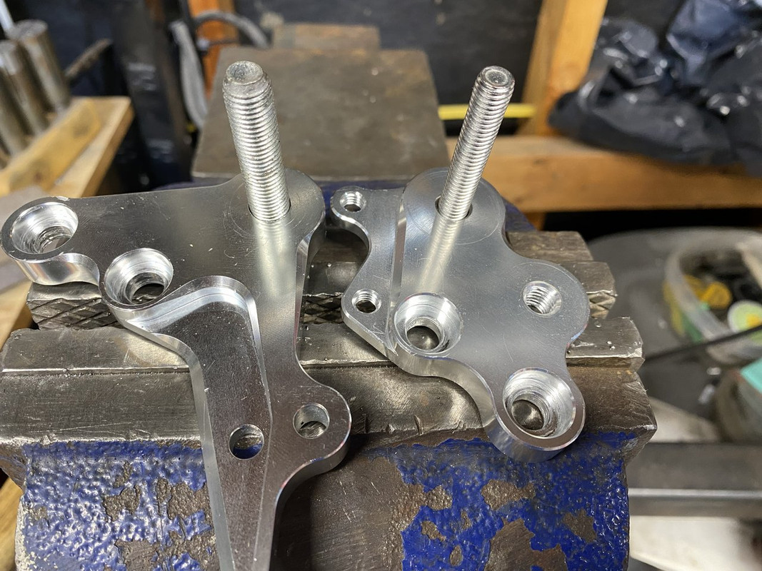
Once the spacers were done, I plunge milled the 5/8” holes in the adapter plate. I did this so the the spacer take some of the load rather than letting the bolts take it all in pure shear.
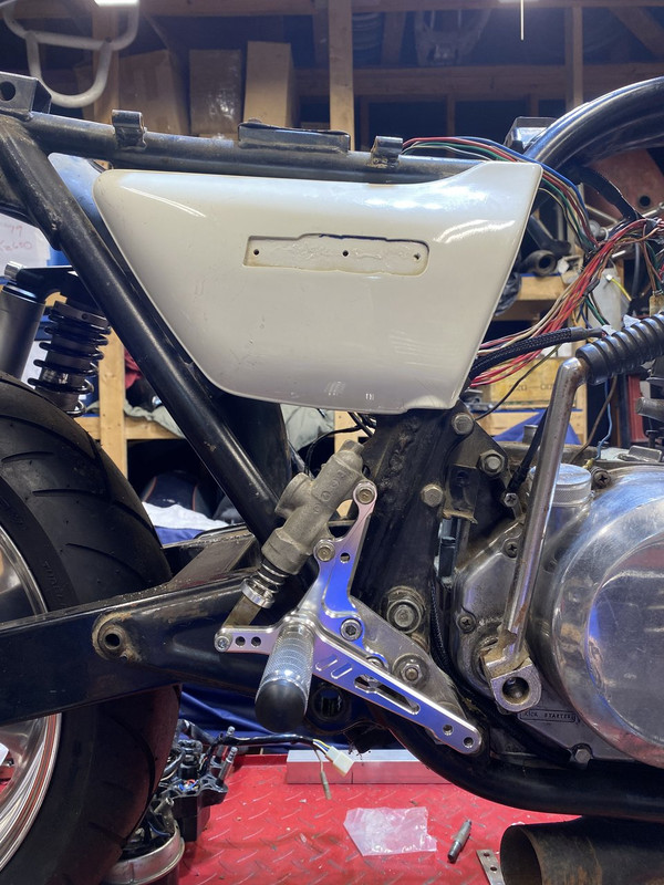
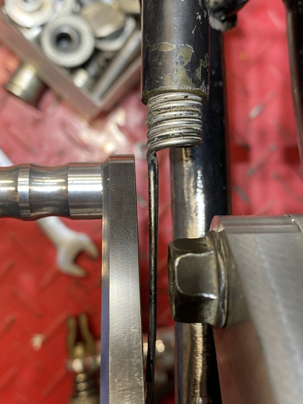
The mounted assembly gives me about 1/8” clearance between the shift lever and sidestand spring.
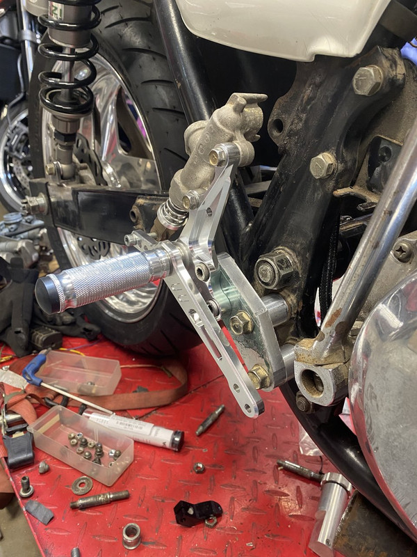
Now I just need to finish shaping the plates and make them pretty. I also may do something to the spacers to dress them up a bit since they are really plain looking.
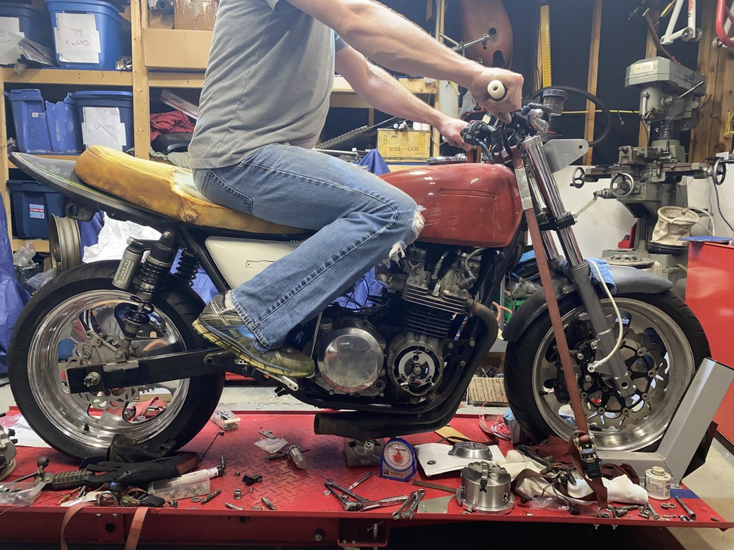
PLEASE don’t mind the big oaf in the seat. He’s just there to make the bike look prettier. Honestly though, with the cut-down seat and new peg position, it’s much easier to squeeze the tank with my knees.
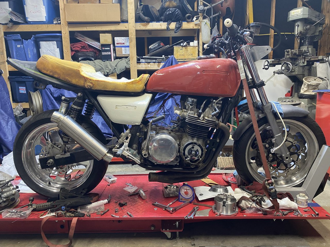
I also couldn’t help but hang the muffler on, too.
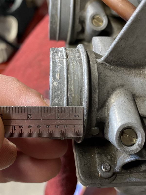
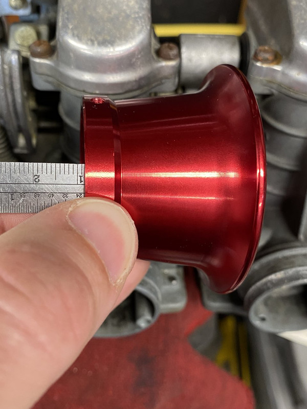
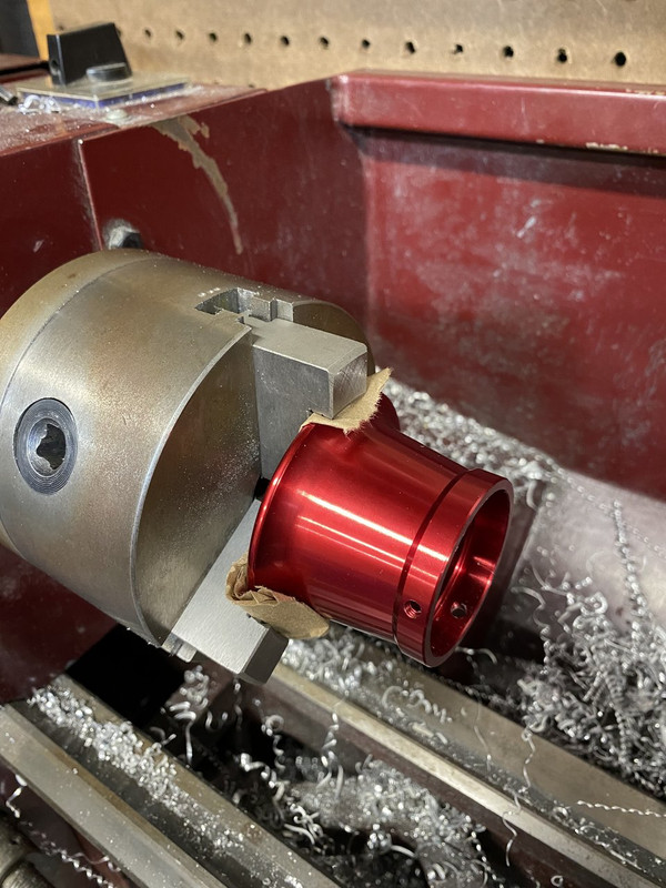
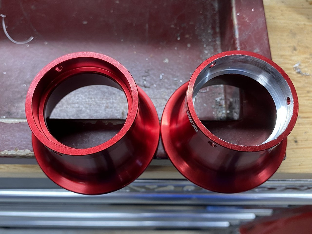
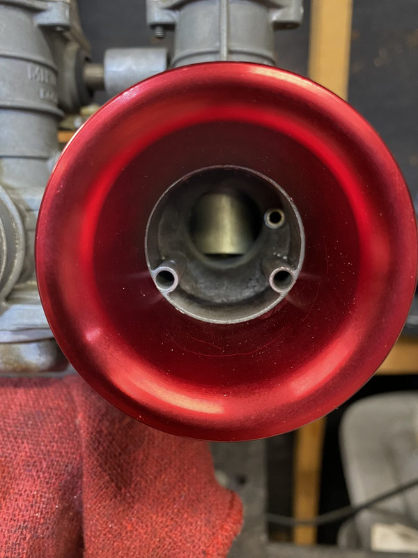
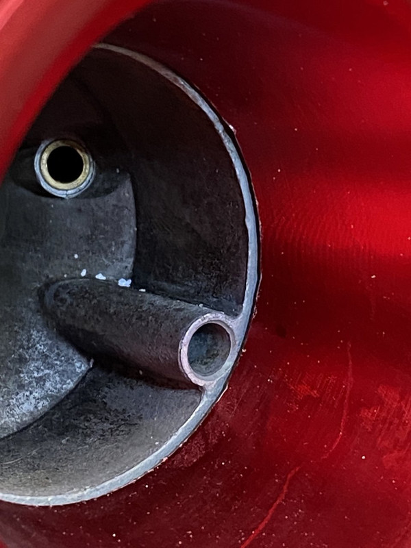
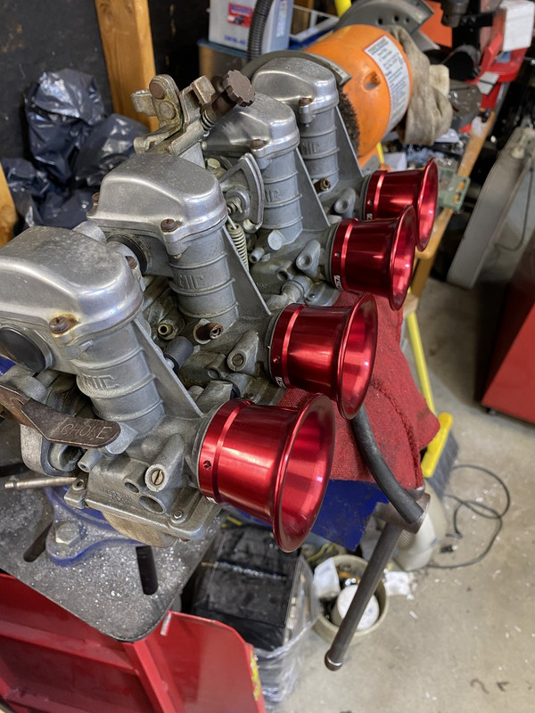
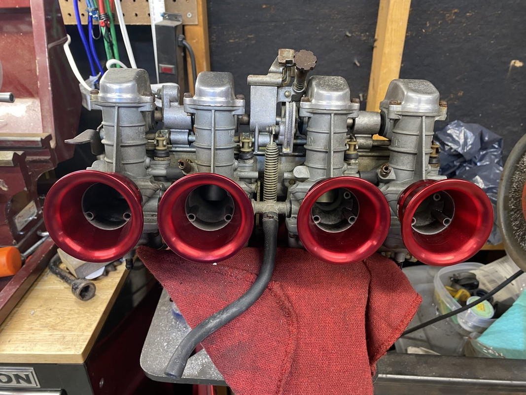
I planned on running pod filters like I’ve done on my Kz1000, but wanted a more “racey” feel and look. So after so internet scouring, I found some velocity stacks on eBay UK. They were selling cheap with a best offer option, so I scored all four for £16 ($21.98 shipped with tax)!! They’re meant for a pocket bike or some other small CC carb, but with about 5mins on the lathe each, they fit perfectly. I bored them from 40mm to 41mm to account for the rib running around the flange and 4.5mm deeper.
For having such a bad situation to start off with the wiring looks real nice man, I will be tackling that on my little bike this summer; seeing you dive into it like that is motivating me to get after my wiring project as well!
I actually enjoy wiring. I do suggest some good crimpers, terminals and connectors, if you don’t already have some. I try really hard not to use the colored bullet and spade terminals from the local parts store. I like factory style connectors where possible.
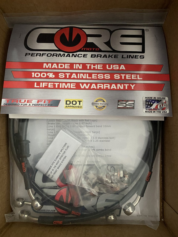
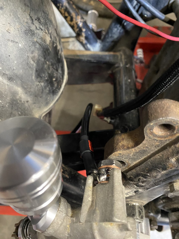
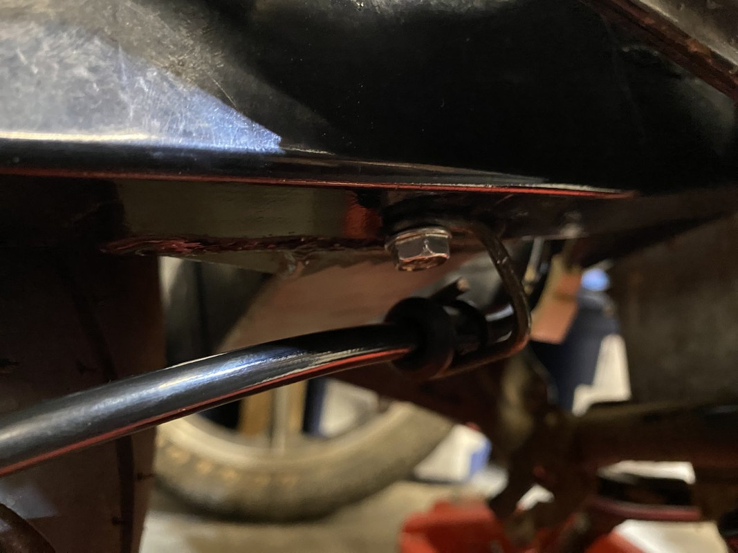
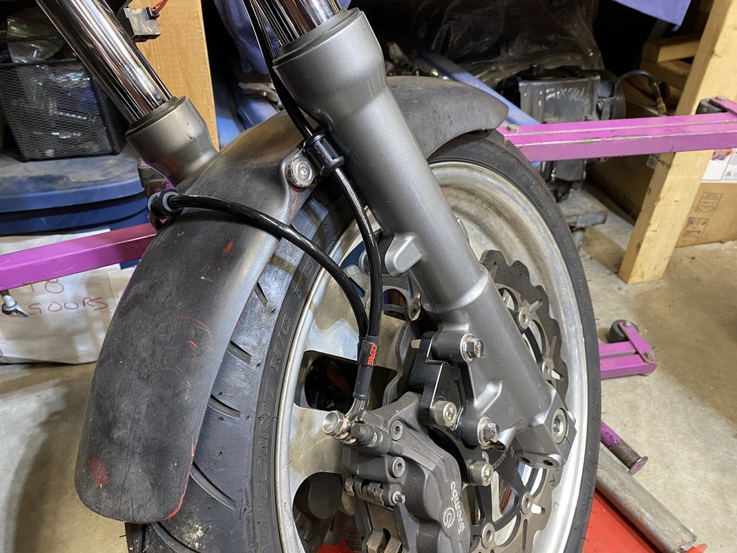
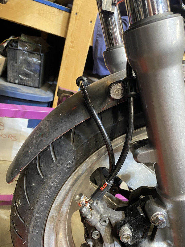
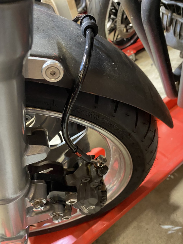
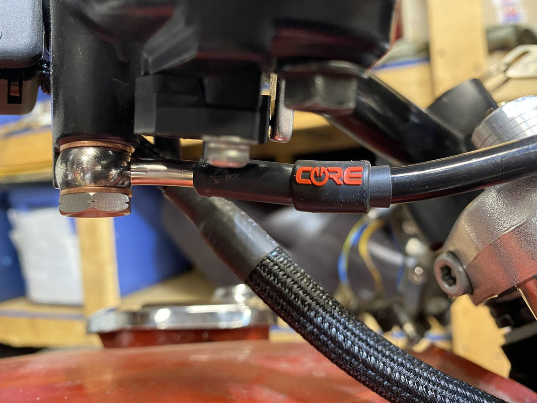
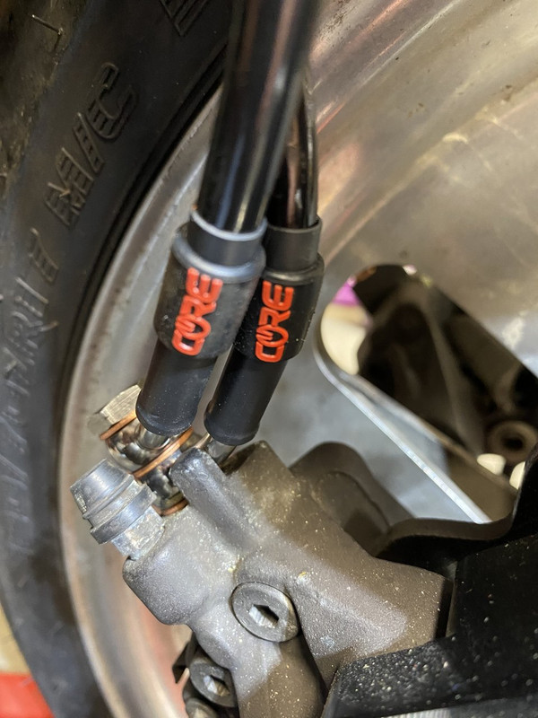
CoreMoto ran a Independence Day sale with 15% all brake lines including custom ones so I jumped on it. I missed their Black Friday sale last year, but wasn’t quite ready anyways.
I have a black rear Brembo coming to match the fronts. The gold one was just a place holder.
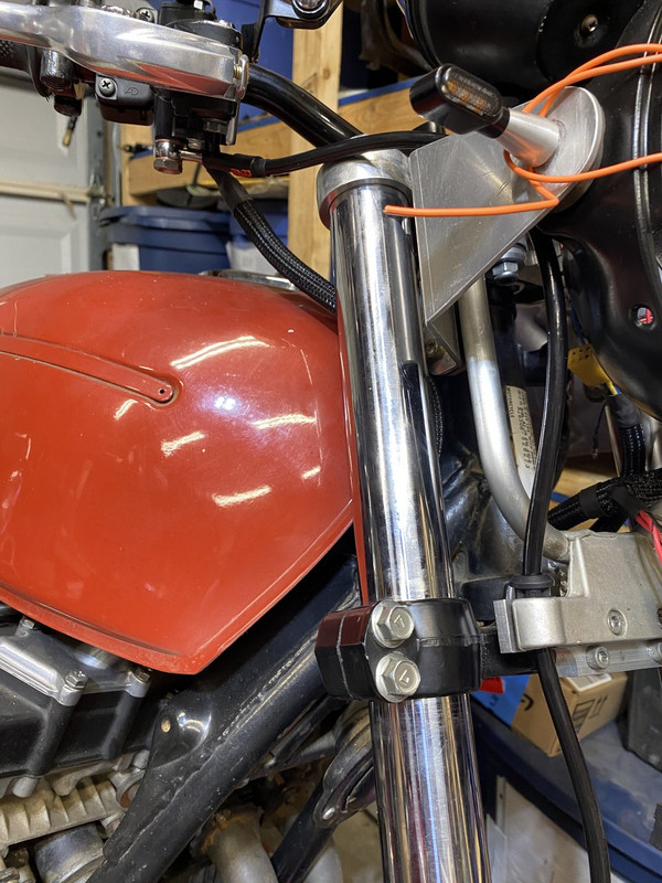
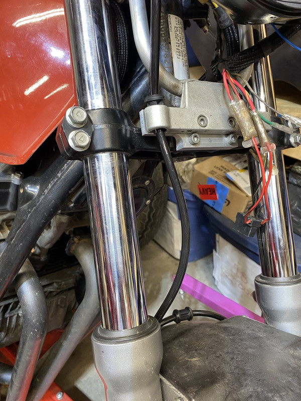
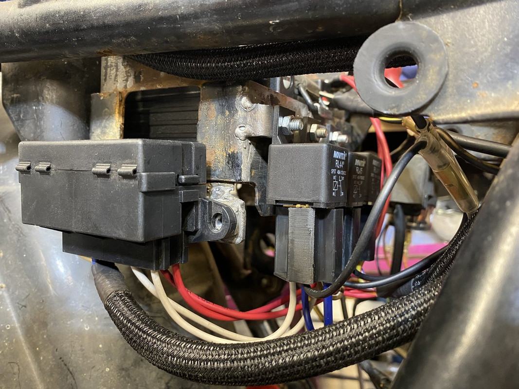
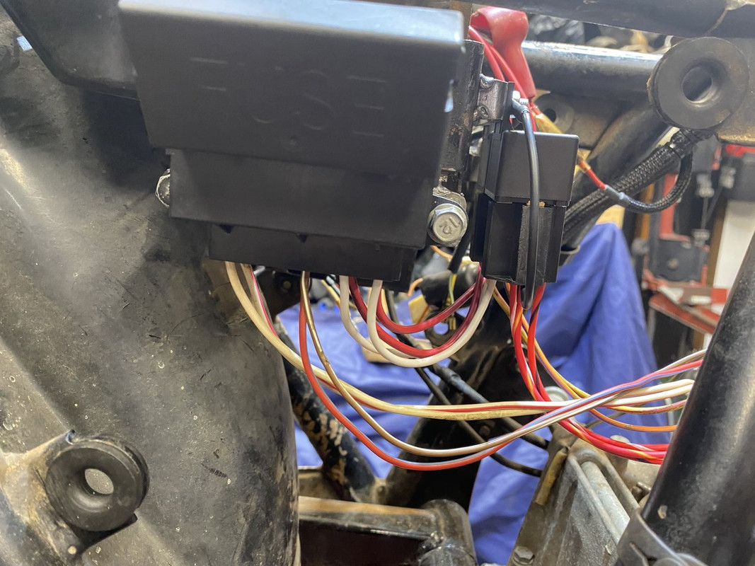
The main harness is done as far as I’m concerned. I had to add a third relay as I wasn’t thinking clearly about my headlight circuit and the headlight was on as soon as I connected the battery…now it’s all good. I need to find some decent harness straps and I hate zip-ties holding harnesses to frames. They’re ok for keeping the harness wrap from undoing, but I like the ability to not cut the zip-ties if I need to move the wiring to get to something.
This site uses cookies to help personalise content, tailor your experience and to keep you logged in if you register.
By continuing to use this site, you are consenting to our use of cookies.

 Honestly though, with the cut-down seat and new peg position, it’s much easier to squeeze the tank with my knees.