Follow along with the video below to see how to install our site as a web app on your home screen.
Note: This feature currently requires accessing the site using the built-in Safari browser.
We noticed you are blocking ads. DO THE TON only works with community supporters. Most are active members of the site with small businesses. Please consider disabling your ad blocking tool and checking out the businesses that help keep our site up and free.
wow that sim is very cool and tells more than my keybord can,butteye can try
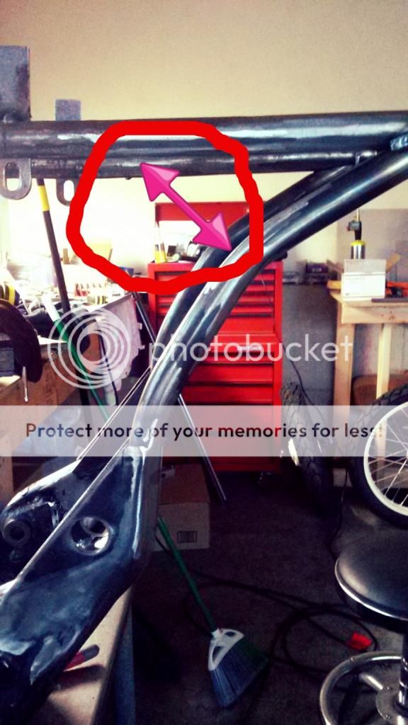
it just wont work unless the rocker is totally re-located lower and forward somewhere above the swinger main pivot
you must have the actuation from the swinger to be AIMED in the direction of the MOST active motion, which is far from what you have now
what you are looking for is a rising rate that is as the wheel comes up it starts loosing advantage on the shock,in other words the further into wheel travel you get the more shock travel you get
even a slight change in rate is better than none but idealy the rate is on a curve that steepens near full travel
keep at it !!!! you can do it you got plenty practice so far
You may have to modify your swingarm brace and bellcrank length (red in previous mockup) anyway, to a point where the motion ratio of the swingarm and bellcrank suit the shocks travel
My plan, once I get ready to start fab and mock up on the new parts, is to make a bellcrank model out of some mdf i have laying around, and make the lower arm with multiple holes so I can get the wheel travel to shock movement ratio dialed in. Then I'll use it as a pattern to finish fab the new bellcrank. Dualero and arkcom, if it's ok, I may pm you guys pics of the mock up for opinions.
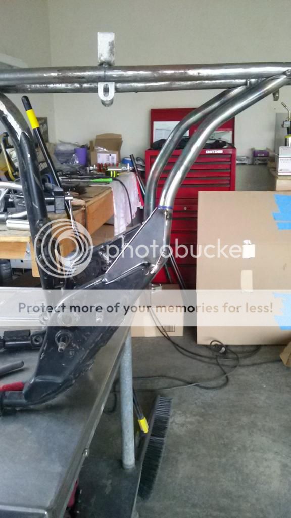
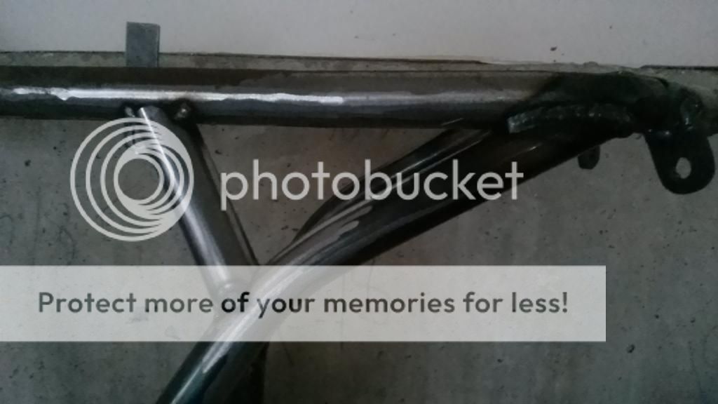
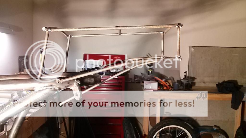
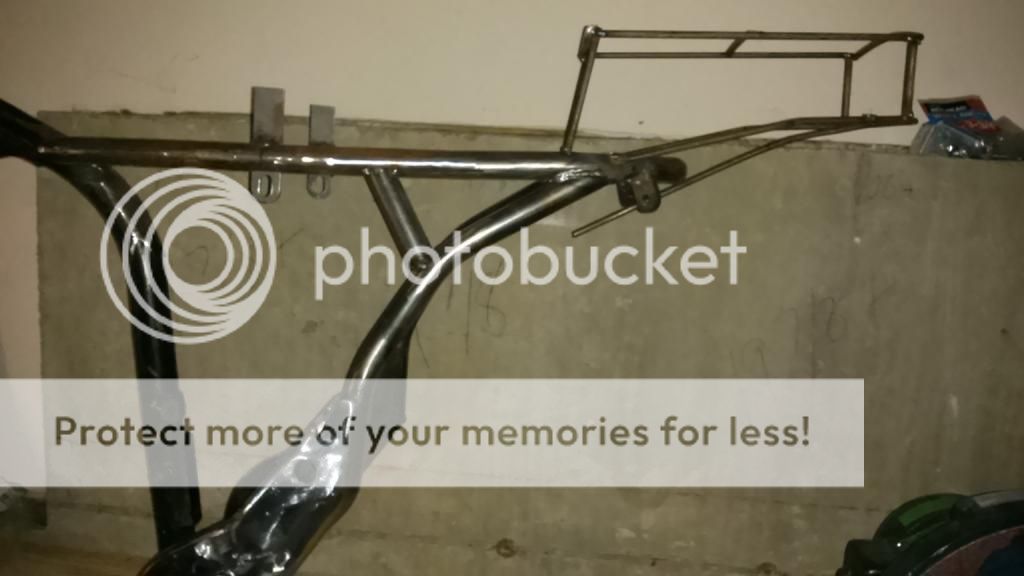
Just need to do the other side, then all the finish welding and grinding and the rear frame will be done.
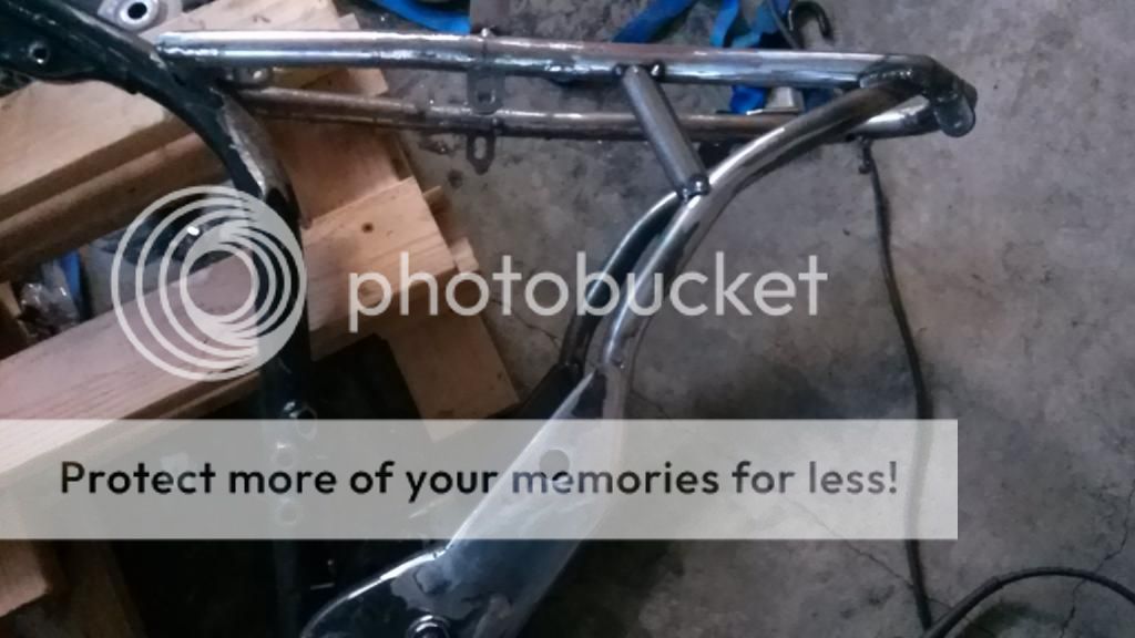
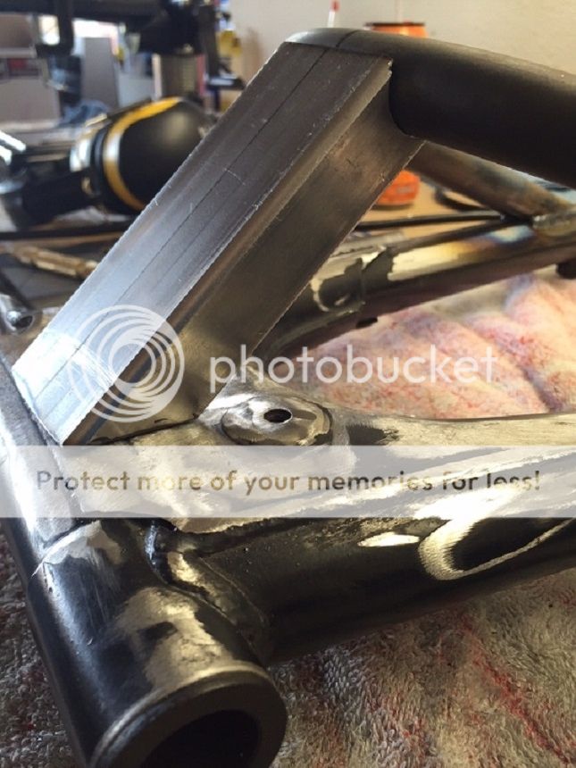
Before..
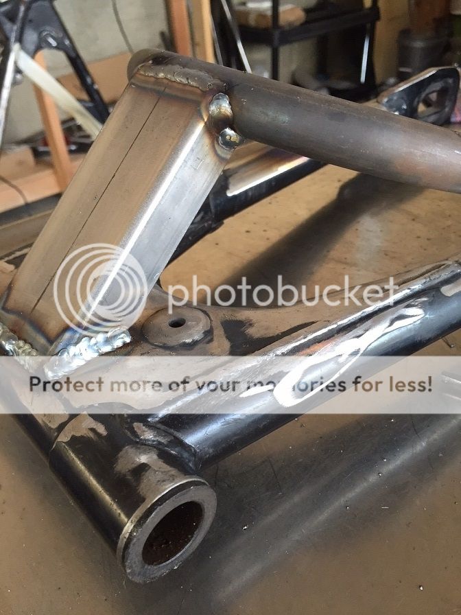
...And after, much cleaner
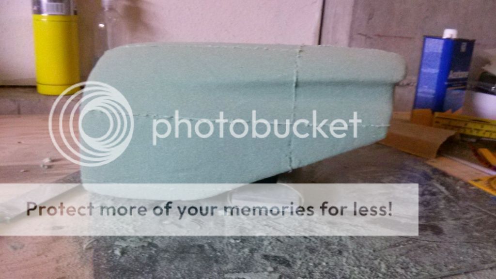
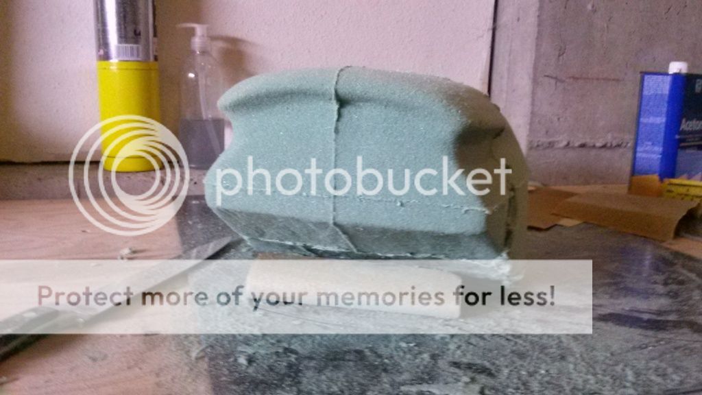
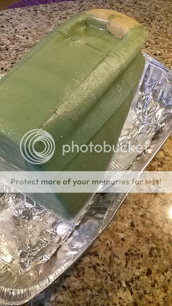
I've been trying to decide on a style or a direction for this build. I finally decided to lean towards a cafe-ish type bike. The actual tail section will have a lot of slight curves and "flavor" and will be made out of fiberglass. I made up a quick mock up of a tail section, just soI can get an idea visually of dimensions and a general overall shape.
I believe you've taken many liberties with that frame. It looks swell, I just hope it holds up to the task (strength and rigidity).
I can only imagine what you have in your mind for the tail section. It's not bad - it's quite nice actually, more of an 80's superbike sort of thing - but my heart is set on the older school, curvier tails...
(You're mighty handy with a torch and a welding machine, aren't you???)
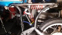
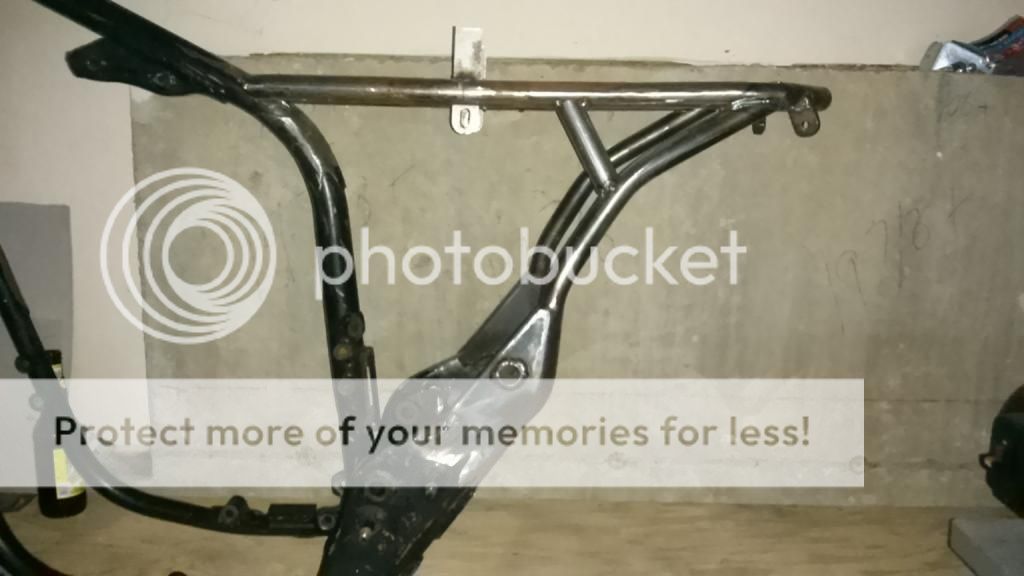
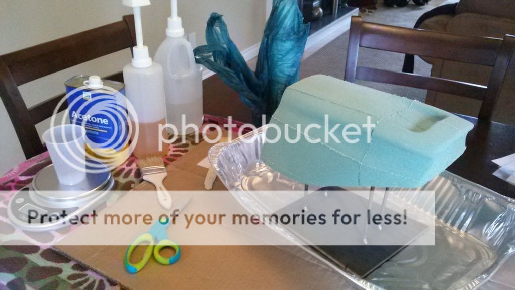
Finally got the rear suspension sorted out, just waiting in the final bits to arrive in the mail so I can finish fabing up all the parts. I re did the rear sub frame and mounting for the shock, cleaned it up a bit. While I'm waiting for the material to show up for the fabing of the bellcrank and the rest of the rear suspension, I started on a tail section. The actual thread is over in the Tanks and Seats section, but I thought I would at least post the highlights here.
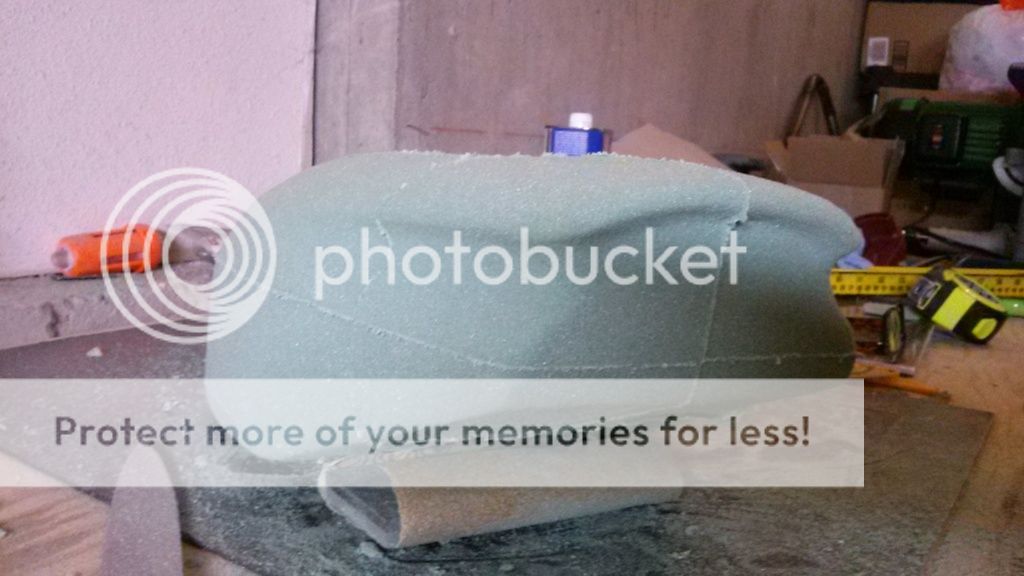
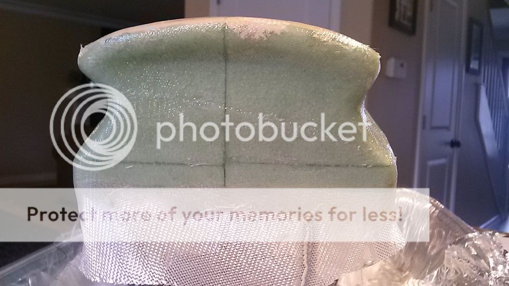
I went thru 3 different iterations of the tail before I settled on this one. A little more refining and smoothing and it'll be ready for fiberglass.
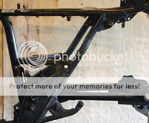
So I've spent the last couple of months re doing the rear section of the frame. I wasn't happy with the way it turned out and the mounts I used for the rear shock looked like a second thought just added on and didn't flow with the frame the way I wanted. I also decided to make a tail section and wanted the frame to a kick up at the end instead of being flat like it was.
The actuation of the rear shock needed to be re done as well to make it function proper and to make it safe. To do that, I re did the bellcrank, the swingarm brace and the push rod mount on the swingarm brace.
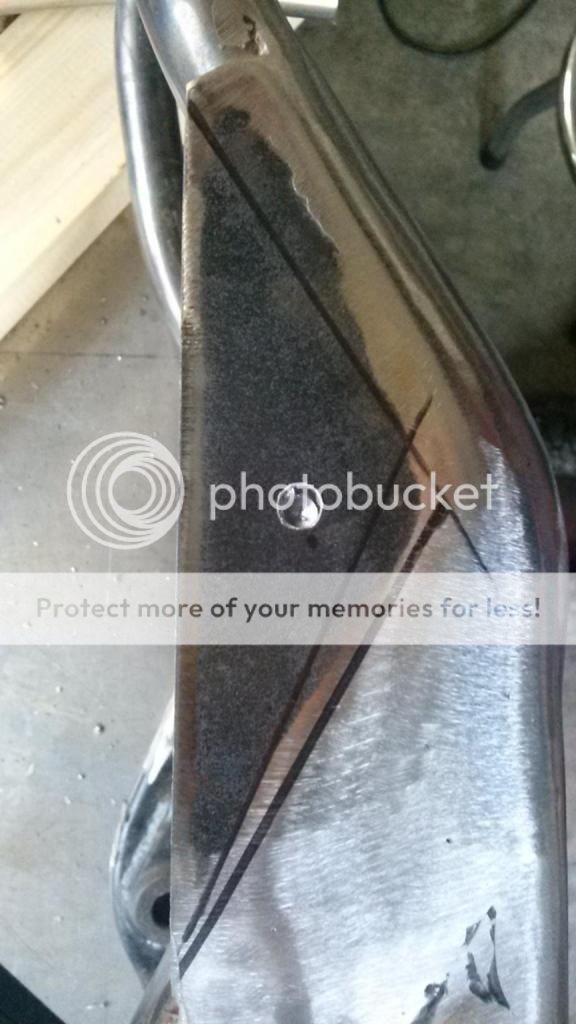
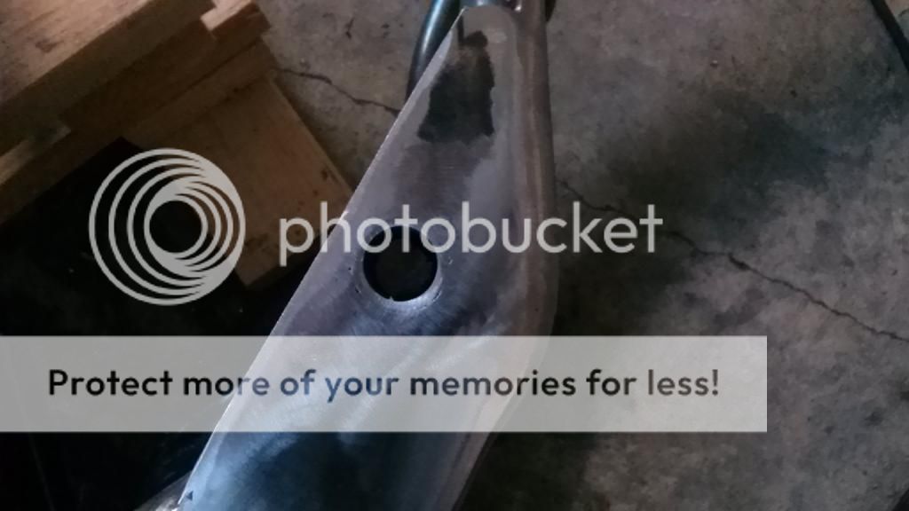
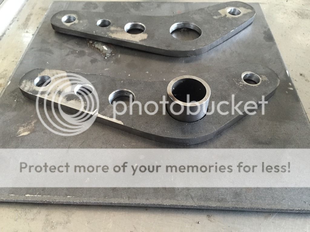
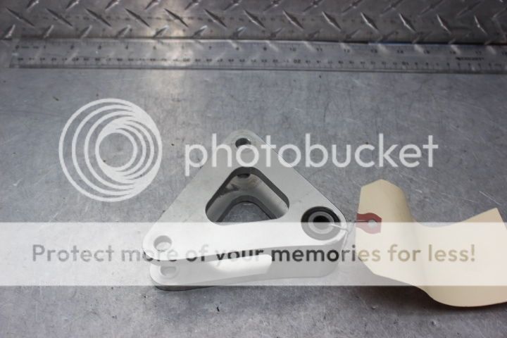
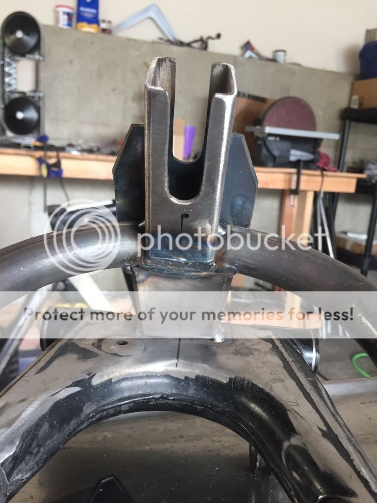
For the bellcrank I fab'd up the two sides out of 1/4 inch plate, the large hole in the center will hold a needle bearing for the pivot of the whole unit. There's still some fab to do with mounting points for the shock and the push rod but this is the new shape..
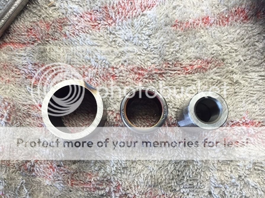
Sleeve, needle bearing and bolt sleeve
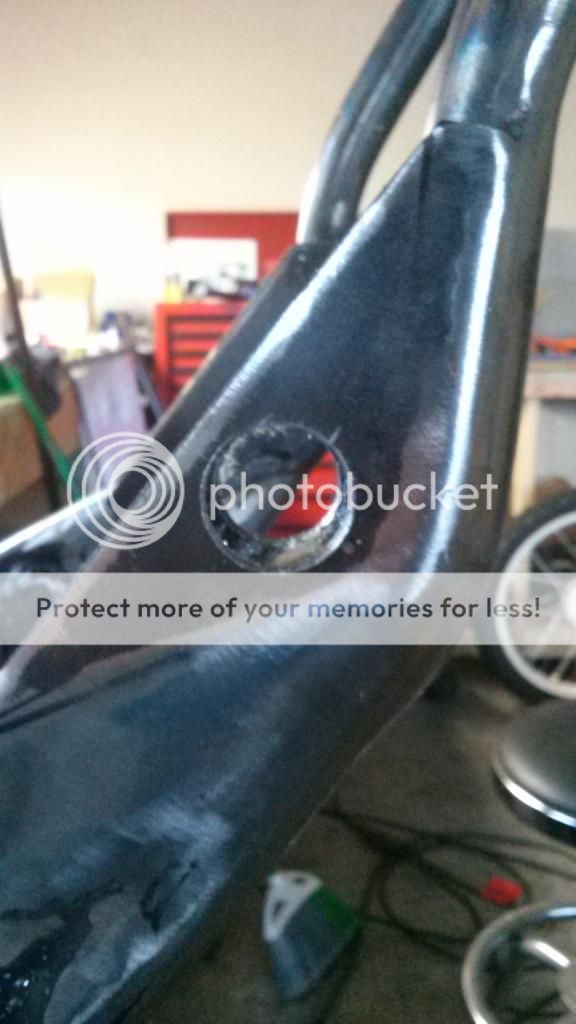
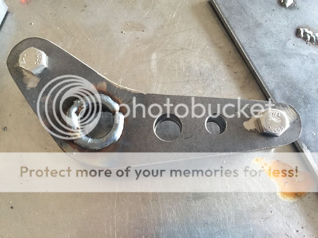
Tacked the sleeve for the bearing on the inside of one the plates to set the position, didn't get a pic of that..
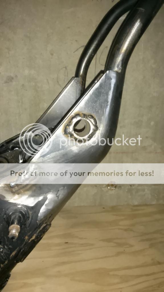
Lined up the two sides with a couple of bolts and nuts for spacers and welded the sleeve to the bellcrank. It will be ground smooth
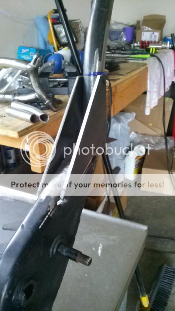
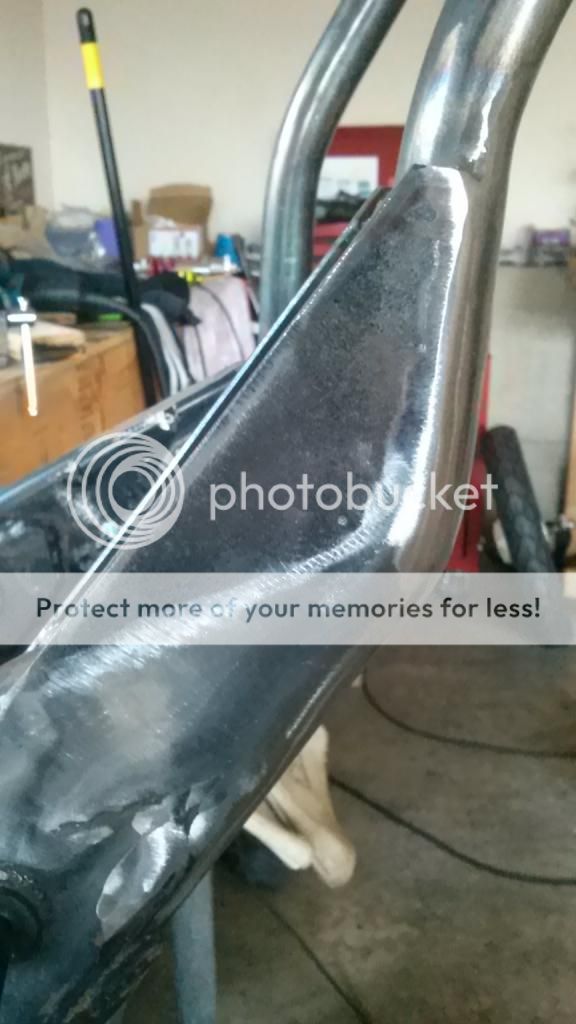
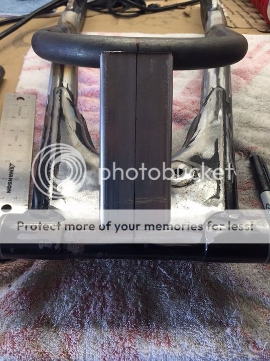
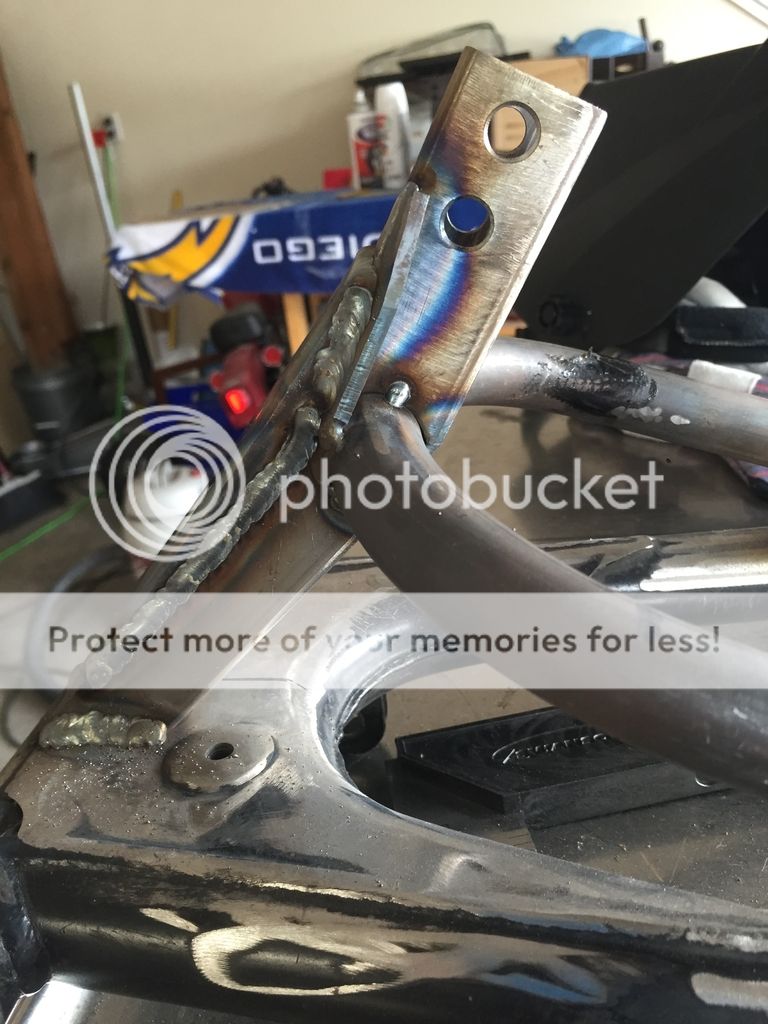
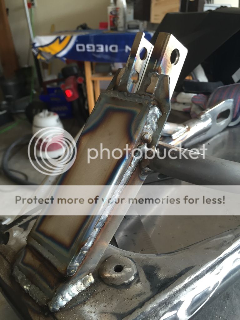
Worked on the swingarm brace and pushrod mount next. I welded a new hoop section on then added a brace for the front using some 1x2 stock.
Made a mount for the heim joint (rod end) that will be on the end of the pushrod for adjustability. Didn't get any pics of the mount but I used some 1 1/4 square tubing, notched it, and drilled two holes so I can move the pushrod up or down if needed to keep the relation to the bellcrank at the right angle. Also added some gussets on the side of the square mount tying it into the tubing of the brace, then cut a gusset out of the 1x2 to connect the front brace to the mount for the pushrod, tying them all together. A little overkill, but this will be a high stress area so I want it to be strong. Still need to do some shaping and grinding to make it all purty
I'll be fitting and welding a gusset tying the back side together too
This site uses cookies to help personalise content, tailor your experience and to keep you logged in if you register.
By continuing to use this site, you are consenting to our use of cookies.

")