RoyalRider
2010 Royal Enfield Bullet 500 - 1982 Honda CB125s
Hi everyone,
I have a '82 CB125S that I am working on and planning on turning into a nice little Cafe. I have done some work on it already and hope to make a detailed post over in the projects section once it is completed. When I bought it, it did not run and did not have front brakes. I have since returned the engine to running condition with a new carb and have replaced the front brake cable, front and rear brake drum shoes, installed new clutch plates, and installed a new gasket on the clutch side engine case.
I have already read the guides that other dudes have posted here on how to do a 12v conversion but most of them are for the 70s era version. They have different regulator/rectifier units and no CDI pulse generator like mine does.
Here is my problem and what I need help with : the original rectifier/regulator has 5 wires leaving it and my new rectifier only has 4 prongs for wires to be installed.
Here are pictures of the old R/R with the new R/R as well as a picture of my bike's wiring diagram : http://imgur.com/a/RZt8K#0
I was hoping to cut the wires coming out of the old R/R and fabricate some prong-type connectors to reconnect them to the new R/R so they can connect to the original wiring loom.
As you can see the yellow and pink wires come from the alternator. I can't join them together and place them on the 4th prong as that might short out the alternator (or so I was told. I am very bad at electrical business so please bear with me).
My guess is that one of these 5 wires can probably act as a ground and might not need to be connected to the new R/R unit. I need to figure out which one but I suck at everything electrical...
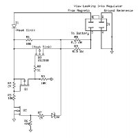
Furthermore, I am not sure how the internal wiring of the new R/R unit works and if it even matters. The new R/R was purchased from Ebay and has zero information other than it's a silicon based model and was meant for small displacement scooters/motorcycles up to I believe 150cc.
This diagram : http://i905.photobucket.com/albums/ac258/bashan_2010/Technical_2/Rectifier_Pin_Out-1-1.jpg supposedly shows the inner workings of the R/R but in the same thread that this diagram was posted someone mentioned that the top left yellow can sometimes be switched with the top right red.
I have tried to use my multimeter to test out the R/R according to this diagram and am not getting readings...it's possible I waited a month for this R/R to arrive and it's a complete dud.
Any help is much appreciated, I understand that these sort of gremlins are not easy to get rid of and without being to see what I'm working with it might be hard to help me out. I'll take anything I can get because without the lights working I can't pass safety with this bike which is keeping me from doing any major work on the project.
Thanks for reading")
I have a '82 CB125S that I am working on and planning on turning into a nice little Cafe. I have done some work on it already and hope to make a detailed post over in the projects section once it is completed. When I bought it, it did not run and did not have front brakes. I have since returned the engine to running condition with a new carb and have replaced the front brake cable, front and rear brake drum shoes, installed new clutch plates, and installed a new gasket on the clutch side engine case.
I have already read the guides that other dudes have posted here on how to do a 12v conversion but most of them are for the 70s era version. They have different regulator/rectifier units and no CDI pulse generator like mine does.
Here is my problem and what I need help with : the original rectifier/regulator has 5 wires leaving it and my new rectifier only has 4 prongs for wires to be installed.
Here are pictures of the old R/R with the new R/R as well as a picture of my bike's wiring diagram : http://imgur.com/a/RZt8K#0
I was hoping to cut the wires coming out of the old R/R and fabricate some prong-type connectors to reconnect them to the new R/R so they can connect to the original wiring loom.
As you can see the yellow and pink wires come from the alternator. I can't join them together and place them on the 4th prong as that might short out the alternator (or so I was told. I am very bad at electrical business so please bear with me).
My guess is that one of these 5 wires can probably act as a ground and might not need to be connected to the new R/R unit. I need to figure out which one but I suck at everything electrical...
Furthermore, I am not sure how the internal wiring of the new R/R unit works and if it even matters. The new R/R was purchased from Ebay and has zero information other than it's a silicon based model and was meant for small displacement scooters/motorcycles up to I believe 150cc.
This diagram : http://i905.photobucket.com/albums/ac258/bashan_2010/Technical_2/Rectifier_Pin_Out-1-1.jpg supposedly shows the inner workings of the R/R but in the same thread that this diagram was posted someone mentioned that the top left yellow can sometimes be switched with the top right red.
I have tried to use my multimeter to test out the R/R according to this diagram and am not getting readings...it's possible I waited a month for this R/R to arrive and it's a complete dud.
Any help is much appreciated, I understand that these sort of gremlins are not easy to get rid of and without being to see what I'm working with it might be hard to help me out. I'll take anything I can get because without the lights working I can't pass safety with this bike which is keeping me from doing any major work on the project.
Thanks for reading