Found some install instructions. I wonder if the Dyna Tach Adapter is just two 10ohm resistors?
http://www.dragspecialties.com/pdfs/19086840.pdf
6. Locate the OEM wires for the turn signals. Usually they
are brown and violet wires.
NOTE: You will notice only one bulb for the turn signals in
the gauge and two wires from the bike to the harness. If you
connect both of these wires directly to the yellow wire on the
speedometer, this will allow feedback and cause all the signals
to flash at once. To prevent this, you will need to add a diode
between each OEM turn signal wire and the yellow wire
coming from the speedometer. We recommend that you utilize
a Dyna tach adapter, Part #D-101, available separately.
This tach adapter includes the diodes necessary to allow the
turn signal indicator light to operate correctly. Follow the
instructions for the tach adapter, substituting the wires from
the original wire harness found in step 6 for the two ignition
terminals shown in the wire schematic. Hook the white wire
on the tach adapter to the yellow wire for the turn signal
indicator on the speedometer. If you use the D-101 adapter,
skip steps 7-9 and go directly to step 10.
7. Take one of the diodes, making sure to observe the correct
polarity, and attach it to the brown turn signal wire on
the bike.
8. Take the remaining diode, again making sure to observe
the correct polarity, and attach it to the violet turn signal
wire on the bike.
9. Take the remaining wire from both diodes and attach
it to the yellow wire on the speedometer.
http://www.customled.com/products/flasher_relay/flasher_relay.htm
http://www.knucklebusterinc.com/features/wp-content/2008/04/ledfig2-1.gif
From SOHC4 Forums:
DHolbrook
[quote author=DHolbrook]
You are correct across the board, you'll need to install a diode on each turn signal wire before it reaches your indicator light. I went to radio shack and bought a diode that had the lowest rated Peak Inverse Voltage. I think the diode itself was 100 watts. It was only $1.65 for two. I went home and altered my connections like so:
I soldered a diode into each signal power feed.
I choose one of the two wires running to my dash light to be a power and the other to be a ground.
I ground the ground wire I choose for the idiot light.
I connected together the two power leads from the signal sides after they traveled through the diode, to the power lead to the dash light. Three wires all together.
Turned the key, hit the switch, and everything worked. I had my headlight on so fast after that!
[/quote]
[quote author=TwoTired]
You want to use the rectifier diodes.
[/quote]
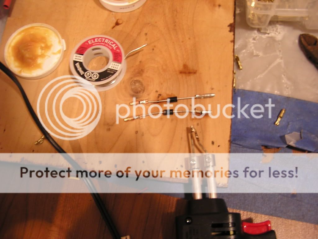
[quote author=jessezm]
And we have VICTORY! I used the rectifier diodes, crimped, soldered, and heat shrinked. I used a brass connector for the ends feeding the indicator light, and a silver connector for the ends coming from the blinker leads. Then I used a 2-into-1 connection (not soldered) for the two brass ends to feed into the indicator light. Works like a charm!
[/quote]
Would've been easier just to link the SOHC4 Forum thread but I figured this would help others more easily.