Follow along with the video below to see how to install our site as a web app on your home screen.
Note: This feature currently requires accessing the site using the built-in Safari browser.
We noticed you are blocking ads. DO THE TON only works with community supporters. Most are active members of the site with small businesses. Please consider disabling your ad blocking tool and checking out the businesses that help keep our site up and free.
the online manual i have isn't very helpful on the reassembly of the cam chain sprocket/valves/initial timing other than....
1."LT" to stator aligning mark for left cylinder TDC
2. align cam sprocket cutout "L" with cam case
3. mount cam sprocket with 2 6mm bolts.
that's it.
so when i assemble the sprocket on the cam, the cam is TDC of Exhaust Stroke on left cylinder's TDC....is this correct?
i'm assuming this "is" correct since the sprocket's shouldered 6mm bolt only goes into one hole and the full-threaded bolt only goes into the other hole (since the manufacturer put them slightly out of alignment on my cam/sprocket). i've rebuilt and timed car motors before, but typically TDC is on the Compression stroke not the exhaust stroke and my manual doesn't mention this fact.
any help would really be appreciated.
thanks in advance
greg
Lobes up or down on the cam doesn't matter as the cam turns only once for every two rotations of the crank. This means the sometimes the lobes will be up at LT and sometimes they'll be down. There is no exhaust or compression stroke until the cam is installed. It's just TDC, BDC, etc. Just aim to get the cam sprocket level with the top of the head when the stator is on the LT mark.
thanks, i appreciate it i was over thinking and making things more complicated than they seemed but i didn't want to button it up and find out i was wrong.
thanks again. and yes....the pin faces up and its the only possible direction when the other steps are followed. lobes point up, pin points up L/line is horizontal while left cylinder is at TDC.....no matter how many times i tried to screw it up, i kept coming back to this way of doing it.
but i realized why i was confusing myself. i was combining valve adjustment on TDC of compression stroke and this assembly has nothing to do with that.
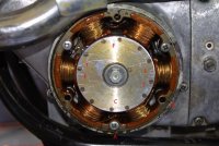
If you guy are still around. I'm in the same boat on a rebuild with my CL350. For some reason this 68' did't have a TDC mark on the stator? See picture .How do I find TDC to install cam to timing chain? Thanks
The line after F is T for top dead center.
Static timing is only about 6~10 degrees before TDC, (the F mark)
The advancer moves points cam to about 32 degrees
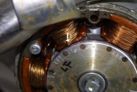
Dude, that's some memory. Have a look at this picture if it is what you are talking about, I think it is. So with the left side piston at the top and the F line - that would be the spot for the timing chain?
Okay, thanks. I think I have it. Only now when I rotate the motor I hearing a click just as the piston snaps back down off the lobes. I think it is "slack" in the chain sense the chain tension is not in yet. How do I know if the valves are not touching the heads? other that looking in the spark plug holes? Is there some visual line up? Thanks again! :-\
this "online" manual you're referring to... what exactly is it? is this going to be one of those things where you destroy an engine because you didn't want to spend $35 on a clymer manual? a good manual will explain how to line up the cam properly. if it doesn't, get another manual
well, davetjones? i haven't read this thread in a while and i see you went with it....how's yours coming? i'm hoping you've figured it out and have been riding!
This site uses cookies to help personalise content, tailor your experience and to keep you logged in if you register.
By continuing to use this site, you are consenting to our use of cookies.


")


