Follow along with the video below to see how to install our site as a web app on your home screen.
Note: This feature currently requires accessing the site using the built-in Safari browser.
We noticed you are blocking ads. DO THE TON only works with community supporters. Most are active members of the site with small businesses. Please consider disabling your ad blocking tool and checking out the businesses that help keep our site up and free.
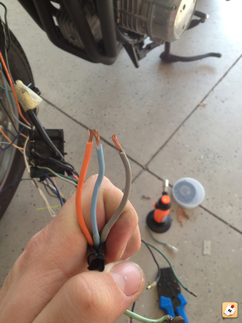
I am trying to connect my idiot light that is inside my DCC speedo. It has a + and - as you would expect. But the stock idiot light has 2 positives! There is ORANGE (O)and LIGHT BLUE (LB) coming from the light bulb. The switch on the handlebars touch the O to a GREY (Gr) or the LB to the Gr. The Gr goes back to the "Winker Relay" and out comes a BLACK (Bk) that goes to a million things.
So my question is, if an LED needs a distinct + and -, how do I connect this?
The idiot light is coming in on the right into a 3-1 connector the others are coming from the blinker and the handle control.
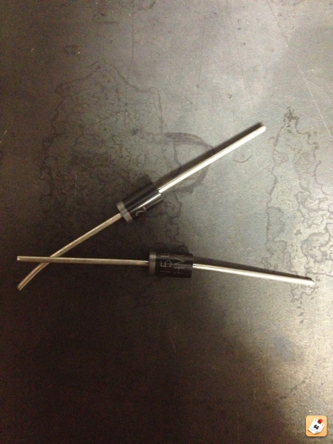
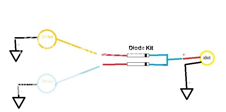
See this post on hondatwins where I found this issue on my bike and how I fixed it. Bottom line is you will have to change the wiring and add some diodes.
This drawing? What is the green and what is the black?
I am sure this will help if I flip it or something, but this diode dealio is for LED blinkers with a standard single idiot light. Mine is the opposite; a single LED idiot light with standard blinker bulbs.
It doesn't matter. The problem is that the stock system is setup to use an incandescent idiot light that allows current to flow in either direction. If you want to use an LED, you will need to modify it with some diodes.
In that pic, you can think of the green circle as your idiot light and the black thing as your harness. The left and right turn wires are the orange and light blue wires.
In that pic, you can think of the green circle as your idiot light and the black thing as your harness. The left and right turn wires are the orange and light blue wires.
That clears it up perfectly, so correct me if I am wrong. I will attach the single side of the diode to the (+) on my idiot light and the double will each connect to the blue and orange wires. Then the (-) on the idiot light just needs to go to ground.
It took me awhile to understand how the stock turn signal circuit worked. Since, when you push the switch to the left, power still flows through the idiot light and through the right turn bulbs to ground. What I didn't realize was that the small idiot light kind of acts like a current funnel and only allows a little bit of current to go to the right side. So even though there is current running through the right side bulbs, it isn't enough to light them up. Odd, but it works. I think diodes were expensive and unreliable back then.
Not that diodes weren't expensive, but the stock setup allowed 1 bulb for the indicator instead of 2. It's a neat solution for a single indicator.
The problem only arises when you replace the incandescent bulbs with LEDs. The small current through the indicator is enough to light leds.
There is another elegant solution. I used 2 small yellow LEDs...they are where the 2 diodes are (LED's are diodes) and stuffed the 2 leds in the indicator housing. So replace the 2 diodes with a 2 small LED's, and you just ground the - leg of the 2 together, both to a ground.
The indicator lens looks the same whether one or the other LED is blinking.
mydlyfk, I recall seeing you write this up on that other forum. That idea is slick, but would only work if it was behind a lens hidding your trick. On mine, the lights are inside of the speedometer and you can see each one.
What kind of sucks is that the shipping is $2.99 for a $2.50 part. Stick some thin bubble wrap around it and shove it in an envelope for $0.80!! I feel like I could make that with $0.50 worth of parts from Radio Shack. Oh well...it is what it is.
And Flug: that must have taken a while to figure out. It makes sense (slightly) when you say it, but holy cow!!
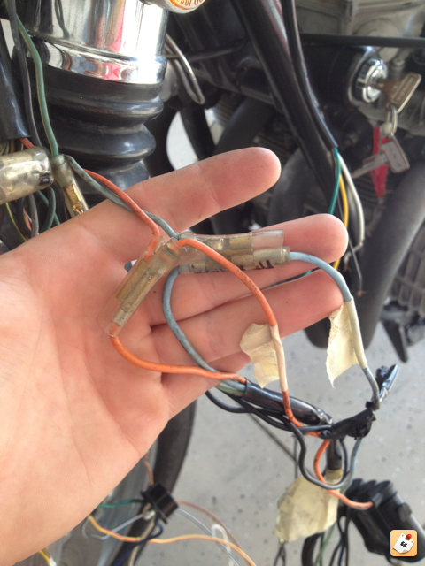
Hey guys, I'm back. I have the piece built as we discussed and connected. Blinkers are all connected now too (well...dangling, not mounted...). When I touch the orange (or blue) wire to the grey wire, the idiot light and the corresponding blinker light turns on...but it stays on, i.e. it doesn't blink. I checked my "winker" relay and there is continuity across the 2 leads. Does that mean it is bad or good?
I also check continuity between the wires at the switch with the ignition off. It was there for both the orange/grey and the blue/grey.
Side note: My switch has a grey common wire. Connecting the blue (or orange) to the grey turn on the respective blinker. The grey wire leads back to the "winker" (blinker) relay. Then a black common wire comes from the winker too.
Update: I grabbed the relay from my dad's bike. Same relay. They still don't flash. I read that if there isn't enough resistance across the relay, it won't work. Is there a chance that the 4 LED idiot lights are the cause?
The only LEDs are the 4 idiot lights I replaced. The turn signals are aftermarket bulbs and the tail light will be replaced with 2 dual element bulbs instead of 1.
This site uses cookies to help personalise content, tailor your experience and to keep you logged in if you register.
By continuing to use this site, you are consenting to our use of cookies.