Flugtechnik
My bike is not transportation, it is a respite
So I have been tossing this idea around in my head for awhile and since I have started rebuilding my engine again, I've decided to actually do something about it. So I am looking for some input from my fellow riders who likely know much more about engines than I do.

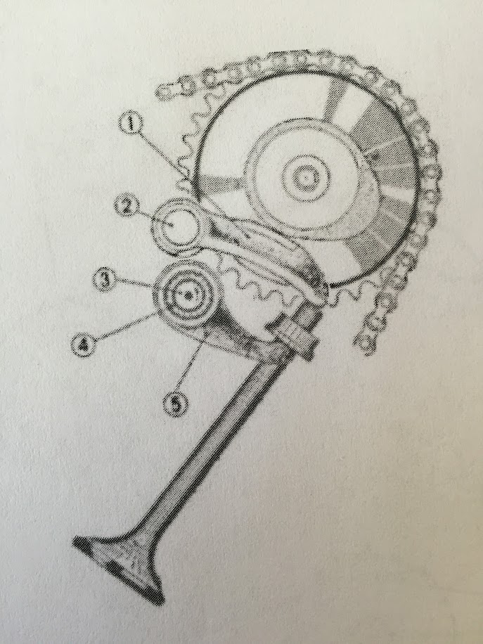
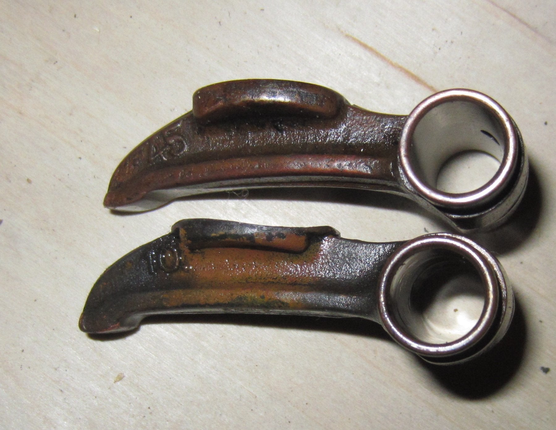
Like many overhead cam engines, the cam followers in the CB450 / CB500T engines have contact pads where the cam actually pushes on and slides across the cam follower. This direct metal to metal sliding contact causes the cam followers to eventually wear so much that they either need to be replaced or resurfaced. For one reason or another, the exhaust cam followers wear out faster than the intake, often lasting less than 10k miles. The geometry of the CB450 valve setup does not allow for much adjustment of the followers as they wear out.
What I am considering is redesigning the cam followers to have a bearing which contacts the spinning cam instead of a stationary contact pad. Below is a rough sketch of what I am thinking.
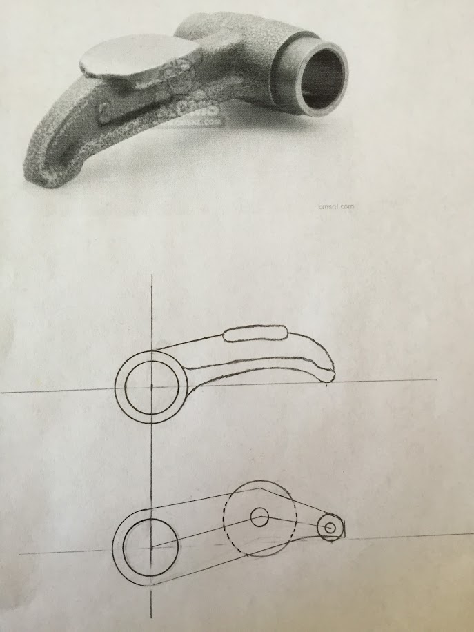
I can do the design work, and even get it made. What I don't know is what type of bearings to use, where to find them, and any pitfalls to this design that I am not aware of.
Like many overhead cam engines, the cam followers in the CB450 / CB500T engines have contact pads where the cam actually pushes on and slides across the cam follower. This direct metal to metal sliding contact causes the cam followers to eventually wear so much that they either need to be replaced or resurfaced. For one reason or another, the exhaust cam followers wear out faster than the intake, often lasting less than 10k miles. The geometry of the CB450 valve setup does not allow for much adjustment of the followers as they wear out.
What I am considering is redesigning the cam followers to have a bearing which contacts the spinning cam instead of a stationary contact pad. Below is a rough sketch of what I am thinking.
I can do the design work, and even get it made. What I don't know is what type of bearings to use, where to find them, and any pitfalls to this design that I am not aware of.


