fiedler.casey
Active Member
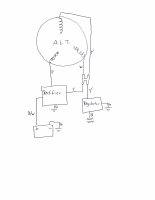
Hey all, I'm wiring my CB360 back together right now and have decided to wire in the old regulator/rectifier (I know you're all going to want to tell me to buy a new one). It would be extremely helpful if someone could clarify a question I've got going on right now. Attached is a wiring diagram of how I've got the charging system put together right now.
The white and yellow from the alternator combine and split to the regulator and rectifier at the same time. I don't understand why this works (it's wired this way stock, too). Doesn't the AC current from the alternator first need to be rectified and then regulated back to 12V before going to charge the battery? Or does the current to the battery not get regulated and is, instead, dumped straight into the batter after simply being rectified. If that be the case, then I need not regulate the current.
All of my wiring is coming from the battery, through the fuses, and then out to load devices. If I'm only sending current from the charging circuit straight back to the battery (as opposed to stock where it appears they regulated the voltage and ran load devices off of that) then do I still need to keep the regulator in the system? I assume the black wire from the regulator goes to load devices, since yellow comes from the alternator/rectifier, and green goes to ground.
One thing I don't understand is how the current passing through the regulator gets rectified, since it's split to the regulator before the AC current from the alternator reaches the rectifier. Then wouldn't the current running out of the regulator (and subsequently to the load devices) be 12V AC? Seems that the only rectified current passes out of the rectified via the R/W wire straight to the battery (though it would be unregulated).
If someone could clear up the function of these two devices as it pertains to the wiring schematic (both stock and my modified wiring), I would be infinitely grateful.