Follow along with the video below to see how to install our site as a web app on your home screen.
Note: This feature currently requires accessing the site using the built-in Safari browser.
We noticed you are blocking ads. DO THE TON only works with community supporters. Most are active members of the site with small businesses. Please consider disabling your ad blocking tool and checking out the businesses that help keep our site up and free.
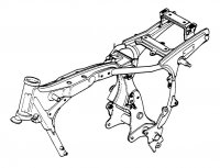
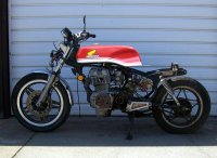
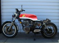
So I'm in the process of building a "café racer" out of a '81 CM400C. As some know there is a serious lack of parts for the CM/CB 400/450 series of bikes. I've been trying to figure out what I was going to do for a tank. This series has an odd frame in that there's a fat portion in the middle of the backbone, @4" wide while the rest of it is @2.5". The fat part makes it so there's not too many tanks to work with.C:\Users\Jim\Pictures\CM Cafe Racer\cm400t.jpg
There is a purpose for the fat section, head bolt access so you can do the top end w/o removing the engine.
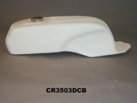
Checked to see if "Glass from the Past"http://caferacingparts.com/ , "Fast from the Past" http://www.fastfromthepast.com/servlet/StoreFront or "Air Tech Streamlining"http://www.airtech-streamlining.com/ had any new tanks made for these. No Joy :cry: So I sent an email off to Airtech asking for suggestions of a tank that I could modify to work. Dutch from Airtech got back to me fairly quickly suggesting using their CR3503DCB Drixton style tank
designed for the CB350 but with concerns about it fitting the frame. I'd already tried dropping the CL350 tank I have on and it doesn't fit. We went back and forth discussing it and Dutch made me an offer that's hard to refuse. He sent the lower tank plate for me to cut and modify to fit my frame as well as the CB450SC (Nighthawk 450). In exchange for this he'll be sending me a complete tank after they make a mold so they'll have a new product to sell.
Received the tank base in 3 days from Dutch
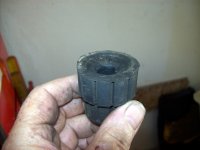
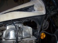
First was a cut, test, cut, test, cut, test day :lol: First thing was to cut the front rubber pucks down since this tank is much narrower as well as the stud.
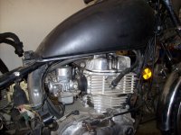
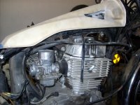
Trial fit time and find that the coil is in the way of the tank.Since I don't plan on using the stock coil anyway a simple removal is in order. I'll be using the GM coil instead. Relocating the OEM coil is problematic since it requires the frame mounting to work correctly. Next is the CDI box which also is interfering with the tank. That's a simple remount or relocate once I get to the electrics.
The final thickness of the rubber pucks is .60" which is a good fit, tight enough to prevent movement and loose enough the tank slides on easily. Now that it's good time for cutting.
Favorite tool, a Dremel with a cutting disc, plastic type in this case. Since this tank plate was designed for the 350 and the 400/450 frame has the fat section in the middle they don't fit together. A series of small cut outs got me to the point the plate barely fit over the frame.
Now time for clearances so the tank cannot make contact with the frame. 1/4" was the desired amount and after trimming repeatedly I ended up here.
I also ended up having to trim around the backside of the puck area since it was in contact with the frame.
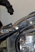
The original rear tank mount has a lip at the rear that if left in place will rub thru the tank so that has to be removed which leaves the mount to be used as a tank support with rubber on top of it if desired.
Since this tank is 25" long and I don't want that mount I cut it out completely.
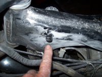
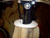
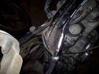
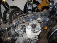
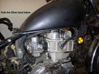
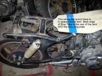
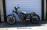
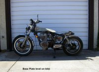
Also needed to remove it to insure the tank clearances are good in case one of Dutch's customers chooses to mount the rear of the tank as low as possible. These pictures show the fitment differences. Look at the rear most wire harness clamp/band (silver) .
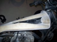
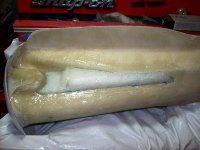
Now that the clearances are good it's time to plug up the holes and reshape the tunnel. Choice of material here is Styrene foam because it breaks off the resin easily and what doesn't come off that way can be removed with gasoline.
Yeah, gas melts the stuff. After shaping I gave it a light coat of resin to fill any void and let it cure overnight.
One note: since fiberglass resin cures by catalytic heat and shrinks in the process it's important to fill the tunnel area so the sides don't pull in and warp.
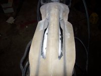
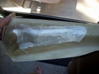
So after curing I cut just enough glass cloth to cover the cutouts plus 1/4-1/2"
and soaked them in resin before applying them.
Couple of important things there. Since I did one side at a time so the area would be flat eliminating any runs of resin I ended up with 2 different ambient temperatures. First side was at @70 degrees so I used the normal amount of catalyst. The other side though was done at @90 degrees so the amount of catalyst was decreased by 15%, hotter ambient means less catalyst. After 100 degrees it's advised to wait for cooler temps. Also this needs a slow setup time since you have multiple angles and absolutely need to work out any air pockets or voids.
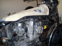
The last 2 pictures were taken as close to the same angle as possible that show how much of the frame will be exposed.
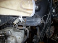
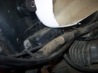
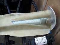
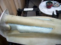
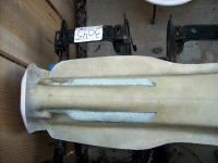
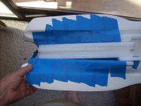
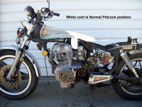
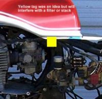
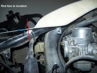
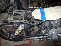
Update: I've completed the glass work and shipped the base plate back. Talked with Dutch yesterday discussing petcock location. The stock position won't work since it's well above the lowest point of the tank. One thought was left side on the low section but that will interfere with a pod filter of velocity stack most likely so we decided to place it in the rear centered on the blue tape, lots of clearance for the frame and backbone there
1st photo is the idea of placement for the petcock, however it'll interfere with an air filter or velocity stack there.
Next 2 shots are the location we decided to run with
This site uses cookies to help personalise content, tailor your experience and to keep you logged in if you register.
By continuing to use this site, you are consenting to our use of cookies.