Follow along with the video below to see how to install our site as a web app on your home screen.
Note: This feature may not be available in some browsers.
We noticed you are blocking ads. DO THE TON only works with community supporters. Most are active members of the site with small businesses. Please consider disabling your ad blocking tool and checking out the businesses that help keep our site up and free.
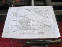
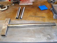
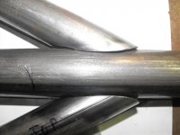
I started (again) on the new chopper this past week. I got the seat post x-member and seat post fish-mouthed and cut, and also mitered the rear wishbones. I'm using the blueprint from the CBH for the CR-200 (Custom Rigid) with wide rear wheel. I'm using a 1.5" backbone instead of the 1.25". I also want to use a single down tube instead of the double tubes running up from the front motor mount. I'll bring the lower rails together just above the front mount and run another 1.5" tube up to the head tube.
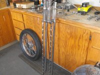
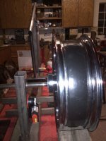
I scored a vintage Randy Enterprises springer fork that is quite long, 34.5" from the lower tree to the rear rocker pivot, so I want to stretch the backbone and down tubes more than what the plan calls for; how much more I don't know yet. I need to get the rear wheel and tire bolted up and then I can mock up the front and get the look I want. I ordered a 18x5.5 rear wheel for the project and I will mount a 180 or 200 tire. I will probably run a chain final drive to keep it narrow.
The springer came with a 18 inch Hallcraft's front wheel and mini drum which I'm selling on ebay. I'll use a 21 inch narrow glide disc brake wheel up front so the bike will stop. I need to shape up the rockers, or build new ones as the original Randy's are a goofy shape (70's). I also need to find a 1"-24tpi die to fix the stem threads as some idiot beat them up for some reason - probably trying to keep the top nut from coming loose I guess.
I'm going to finish the welding jig as I build the frame this time also. When it's done I want to be able to cut, bend and prep the tubes and then be able to assemble them in the jig so they are held in place for tacking (and welding out).
I don't know what motor and trans I'll end up using yet. I would like a shovel, but will probably use an evo due to cost. I may go with a right side drive 6-speed trans also.
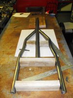
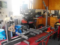
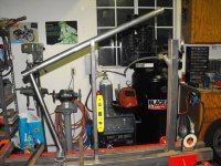
The frame jig...I build this when I built my first frame 10 years ago. The frame is based on a '48 panhead rigid frame that is modified for modern width wheel and taller motors. It's stretched up and out about 4 inches in front and 2 inches back and down in the rear. You can use any neck angle (within reason). For this frame I will use 42 - 44 degrees because I am using a long springer front end.
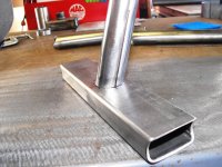
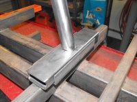
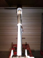
Day 2: I tacked the top tube to the seat post. Then I welded two lengths of 1" angle to the cross bar on the jig to hold the seat post cross member in place. I then wanted a support for the top tube so I set up a length of 1x2 rectangular tube at 25 degrees from horizontal and used a 1.5" hole saw. I then sawed through the center of the hole. I will weld tabs to each side of the pieces and drill and tap them to make a clamp to hold the top tube in place.
As I mentioned earlier I am build the jig as I build the frame so I can reproduce this frame over and over in the future. I am going to make the head tube fixture adjustable so that the rake and height of the head (steering) tube can be changed for different degrees of rake and position. That's next.
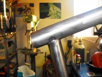
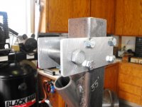
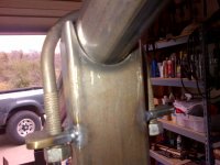
OK another update: Over the past couple of days I got the upright that will hold the back bone (top tube) welded in place between the jig rails and I welded two tabs on either side of the notch at the top of the upright so I could attach a U-bolt (which is actually a 2-1/4" muffler clamp I had laying around) to hold the top tube firmly in place in the notch. I realize that this upright is not adjustable for height at this point, but later on if I want to change it for a different frame I can make it adjustable. I'm trying to do this as simply and inexpensively as possible, so I am trying to use materials from my scrap heap.
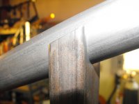
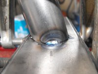
So after I completed that I clamped the tube in and lined everything up. I beveled the bottom of the seat tube and tacked it to the cross member. I then pulled the assembly out and welded it out on the bench. Next I'll attach the rear wishbones to the top tube and then it will be time to bend the lower rails. I may need to get some more tubing as I only have 10 feet left and I'm not sure if I can squeeze both bottom rails out of that or not. I am going to use a single lower down tube from the neck, so maybe...
I also cut and drilled some aluminum plates for the adjustable neck holder. I need to decide whether to use 3/4" round bar or threaded rod for the neck holder. I am thinking of maybe using round bar and boring a 1/4" hole in the end to be used as a pilot hole for a hole saw for cutting the top and bottom tube notches for the neck.
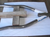
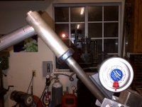
Thank you sir! My bender is a JD Squared Model 3. I have the 1 inch and 1.250 dies for it. It works good as it with no hydraulic power for doing small jobs. I use a 4 foot piece of rectangular tubing for a handle. I am in the process of making a plane of angle mounting clamp for the tube so I can attach an angle finder. I need that to do the bends for the lower tubes as they require rotating the tube a certain number of degrees before making the subsequent bend. I can buy on for $50, but on can be cut from 1/2" steel. I just need to get that done. I'll post a picture as soon as I do.
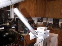
I got another part of the neck fixture done. See pic.
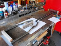
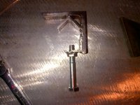
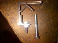
I found this idea out on the web: fab a plane of bend clamp out of angle iron. The large it 2 1/2" and smaller angle is 1". It's not pretty but it will work...better than paying 50 bones for one on ebay. I'm a po mofo! The money is better spent on chopper parts.
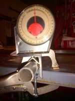
I do need to buy a new angle finder though as this one is crap and I've already glued the needle back on...!
Here is their website with pricing for the bender, dies and other stuff. I bought this one about 10 years ago. The model 3 is now $295 and the dies vary depending on size. http://www.jd2.com/
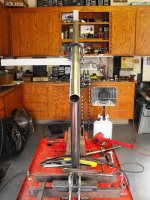
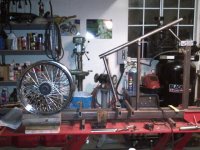
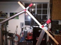
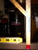
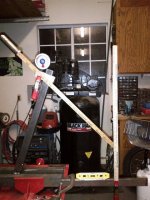
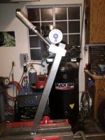
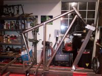
OK a little update. Unfortunately at this stage it doesn't look like much...I angled the neck fixture of the jig forward 20* and then adjusted the steering tube to 45* rake for this 43.5" long springer fork I want to use. I mocked it up with some yardsticks to check the height. I have the top frame tube stretched out another 3" from the plans that I am using, which are already 4" out from a '48 rigid pan frame. Looks like it should fit and look good at this angle...comments?
Looking at the third picture down, you can see that the wheel center is only 9.5 inches off the ground, the small silver sharpie line represents the ground, so that effectively raises my lower frame tubes up.
I know this means my lower rails will be about 4" higher than at the planned height of 5", but when all of the weight is put in, it should come down to it's planned ride height of around 4.5 - 5 inches. Maybe..I hope...
Also mocked up the handlebar riser height and looks like I will need a 12 - 14 inch tall bars to be able to reach them...The springer risers are 6" up from the top of the neck...
Today I printed a template for the miter on the top tube where it meets the head tube and set it back in the jig. The head angle came in at about 42 degrees after I got it all set and I think that will be good. It looks a bit better to my eye than all way out at 45, so i think I'll stick with this for now. I had to do a little filing on the jig and tweaking on the frame top tube to get it aligned perfectly with the head tube when installed in the jig. You need to that with steel after you weld it up as it moves around some.
This site uses cookies to help personalise content, tailor your experience and to keep you logged in if you register.
By continuing to use this site, you are consenting to our use of cookies.
")


