
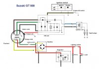
Ok as I've said before I get quite perplexed when I have to tackle anything electrical so could someone answer the following question for me. On the diagram below it shows two light switchs one on the left of the rectifier and one right after the battery why would this be? I only have one switch for the lights on my bike. Also it looks like the ignition side of the system (above the exiter coils) does not have any connection with the battery at all, is that correct? I would appreciate any help.
We noticed you are blocking ads. DO THE TON only works with community supporters. Most are active members of the site with small businesses. Please consider disabling your ad blocking tool and checking out the businesses that help keep our site up and free.
You are using an out of date browser. It may not display this or other websites correctly.
You should upgrade or use an alternative browser.
You should upgrade or use an alternative browser.
Dimwit Needs Clarification On Wiring Diagram
- Thread starter johnu
- Start date
DesmoBro
Busted Nut
Could the second switch in diagram be Hi/Lo beam?.....Is that the entire wire diagram? Hopefully it is and you figure it out quick....My wiring diagram needs 2 electricians (because one isn't enough ,had my buddy over helping last night) My bike turns over and blinkers and everything work but no headlight/back light for the gauges
Hoosier Daddy
Earache my eye...
It's because there is a switch you can turn off the headlights as well as the Hi/lo switch. One leg of the rectifyer on the older suzuki's is opened when the headlamp is switched off. The intent was to prevent over charging.
common mod to bypass it as we all know older bikes charging systems are "margiinal" at best.")
common mod to bypass it as we all know older bikes charging systems are "margiinal" at best.
Ok I got the CDI unit and ran the engine... no problem.
I am still slightly perplexed by the the wiring between the charging coils and the rectifier. I understand about the switch cutting out one leg (green and white wire) of the charging system when the lights are turned off, however I am not using the standard Suzuki handlebar switch and wish to bypass this feature. Originally the green/white wire went from the coil to the handlebar switch and the red/green wire went from the coil to the handlebar switch and to the rectifier and the regulator. Can I now just connect the green/white wire to the same terminal on the rectifier as the red/green wire therefore bypassing the switch?
I am still slightly perplexed by the the wiring between the charging coils and the rectifier. I understand about the switch cutting out one leg (green and white wire) of the charging system when the lights are turned off, however I am not using the standard Suzuki handlebar switch and wish to bypass this feature. Originally the green/white wire went from the coil to the handlebar switch and the red/green wire went from the coil to the handlebar switch and to the rectifier and the regulator. Can I now just connect the green/white wire to the same terminal on the rectifier as the red/green wire therefore bypassing the switch?
Hoosier Daddy
Earache my eye...
Can't you just bypass the switch on the green and white?
Seems to me on my 750 the wire changed color going to and then from the switch, but in your diagram it shows Green / White for both sides of the switch. should be able to simply bypass it at the old switch connections in the harness.
Seems to me on my 750 the wire changed color going to and then from the switch, but in your diagram it shows Green / White for both sides of the switch. should be able to simply bypass it at the old switch connections in the harness.
psychotinner
New Member
Here is a thread from a Suzuki forum that may help.
http://www.suzuki2strokes.com/forum/viewtopic.php?f=2&t=4858
http://www.suzuki2strokes.com/forum/viewtopic.php?f=2&t=4858
Hoosier Daddy said:Can't you just bypass the switch on the green and white?
Seems to me on my 750 the wire changed color going to and then from the switch, but in your diagram it shows Green / White for both sides of the switch. should be able to simply bypass it at the old switch connections in the harness.
It was probably the same as your 750 then with the wire changing color coming back from the switch. Originally the green/white went to the switch from the coil (didn't connect to the rectifier) then I think what happened is it went back through the green/red wire to the rectifier. I think the diagram I posted is a simplified diagram that someone made up.
To bypass the switch I think I can just connect the green/white wire straight from the coil to the same terminal on the rectifier that the green/red wire from the coil is connected to?
Hoosier Daddy
Earache my eye...
I just checked my wiring diagram, W/G tied to a w/r to eliminate the extra wireing and the switch from the circut...


