Sorry to bump this one guys, but this is a great conversation. I'm having this same issue with my Trail Tech Vapor to the point that the tachometer is completely useless. Working with their tech support I've tried wrapping the wire with different numbers of wraps, directly connecting to the negative of the coil signal, different inline resistor values, separate power supply for the Trail Tech...nothing works. It's actually to the point where I can completely disconnect the tach signal wire and the tach continues to bounce around (must be a lot of noise).
I decided to get back to working on building a simple tachometer using an Arduino, so I busted out the scope on the coil / Dyna S. But then I realized I might as well try and get this damn Trail Tech working first.
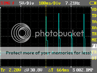
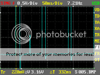
These aren't the best snaps of what is going on, but it helps...
Basically, the negative connection on the primary coil sees about 1v while the coil are powered up (this is with 3 ohm coils, so I'm assuming closer to .6v with 5 ohm coils using a basic voltage divider calculator). When the Dyna S cuts off the ground path to fire the coil, the voltage spikes to 50v+. As the voltage sharply drops back down, there is a little curve around 10v where it looks like it will stabilize the voltage, spikes back up slightly, then it sharply drops again. This drop will sometimes go into a negative voltage, then it will rise back to 1v.
However, I did randomly pick up about a 3v spike that I assume occurs when the other coil fires. I only picked this up on the scope once, so I'm not sure of the magnitude, and I assume it entirely depends on the location of the scope probe.
So, what would be the best circuit to turn this signal into more of a square wave for the Trail Tech to pick up on? I'm basically an idiot when it comes to zener diodes, phototransistors, etc. I'm thinking if a voltage can be sent to the Trail Tech if coil voltage is above 5v, otherwise ground, that might work.